
Since our founding in 2005, MisolTap has established itself as a leading Chinese manufacturer of high-performance thread cutting tools. We integrate R&D, production, and global sales into a seamless operation, providing our clients with robust and precise threading solutions tailored to modern manufacturing needs. In the discipline of precision machining, whether operating advanced CNC milling centers or performing manual bench work, utilizing an accurate thread tap size chart is a fundamental requirement. A miscalculated pre-drill hole will inevitably result in broken tooling, ruined workpieces, and severe production delays.
From our experience supplying tier-one automotive, aerospace, and heavy machinery manufacturers, adhering strictly to a standardized thread tap size chart reduces tool breakage by up to forty percent. The mathematics behind internal threading requires the removal of exact material volumes to accommodate the tap’s cutting edges while leaving sufficient wall thickness for structural integrity. We recommend referencing a verified thread tap size chart before initiating any new production run, regardless of the machinist’s tenure or experience level. This 2026 technical guide provides the definitive thread tap size chart for both metric and imperial measurements, alongside critical insights into selecting the appropriate tooling for your specific application.
Table of Contents
- Summary Table: Core Threading Metrics
- The Engineering Principles Behind the thread tap size chart
- The Complete Metric thread tap size chart (mm)
- The Complete Imperial thread tap size chart (UNC/UNF)
- Selecting the Right Tap Standard: DIN, ISO, and JIS
- Expert Recommendations for Machining
- Frequently Asked Questions (FAQs)
- Industry References
Summary Table: Core Threading Metrics
To provide immediate value for shop floor operators, we have compiled a high-level summary of the most frequently referenced dimensions within the broader thread tap size chart. This table covers the essential metric and imperial dimensions utilized in standard structural fastening.
| Thread Designation | Pitch / TPI | Recommended Drill Size (mm) | Recommended Drill Size (inch) |
|---|---|---|---|
| M4 (Metric Coarse) | 0.70 mm | 3.30 mm | 0.1299 in |
| M6 (Metric Coarse) | 1.00 mm | 5.00 mm | 0.1969 in |
| M8 (Metric Coarse) | 1.25 mm | 6.80 mm | 0.2677 in |
| 1/4″ UNC | 20 TPI | 5.10 mm | #7 (0.2010 in) |
| 3/8″ UNC | 16 TPI | 8.00 mm | 5/16 (0.3125 in) |
The Engineering Principles Behind the thread tap size chart
Understanding how a thread tap size chart is formulated allows machinists to make calculated adjustments when dealing with exotic alloys or thin-walled components. The primary objective of the thread tap size chart is to achieve an optimal percentage of thread engagement. In industrial manufacturing, the standard target for thread engagement is 75 percent. This provides maximum holding strength without placing excessive torque load on the tapping tool.
If you drill a hole too small (resulting in 85 to 100 percent thread engagement), the tap will require immense torque to cut the material, drastically increasing the probability of tool fracture. Conversely, drilling a hole too large (50 to 60 percent engagement) reduces the holding power of the fastener, leading to catastrophic failure under tensile or shear loads. The formula that dictates the metric thread tap size chart is elegantly simple: Drill Size equals Major Diameter minus Pitch. For example, an M8 x 1.25 tap requires a drill size of 6.75mm (commonly rounded to a standard 6.80mm drill bit). We recommend strictly following the specific drill sizes listed in the thread tap size chart below to ensure your assemblies meet global engineering tolerances.
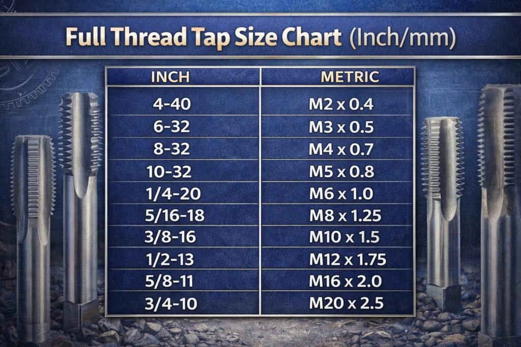
The Complete Metric thread tap size chart (mm)
The metric system utilizes the letter M to denote the thread geometry, followed by the major diameter in millimeters, and then the pitch (the distance between two adjacent thread crests). This metric thread tap size chart represents standard coarse and fine pitches utilized in global manufacturing.
| Metric Tap Size | Pitch (mm) | Tap Drill Size (mm) | Decimal Equivalent (inch) |
|---|---|---|---|
| M2 | 0.40 | 1.60 | 0.0630 |
| M2.5 | 0.45 | 2.05 | 0.0807 |
| M3 | 0.50 | 2.50 | 0.0984 |
| M4 | 0.70 | 3.30 | 0.1299 |
| M5 | 0.80 | 4.20 | 0.1654 |
| M6 | 1.00 | 5.00 | 0.1969 |
| M8 | 1.25 | 6.80 | 0.2677 |
| M8 Fine | 1.00 | 7.00 | 0.2756 |
| M10 | 1.50 | 8.50 | 0.3346 |
| M10 Fine | 1.25 | 8.80 | 0.3465 |
| M12 | 1.75 | 10.20 | 0.4016 |
| M12 Fine | 1.25 | 10.80 | 0.4252 |
| M16 | 2.00 | 14.00 | 0.5512 |
| M20 | 2.50 | 17.50 | 0.6890 |
The Complete Imperial thread tap size chart (UNC/UNF)
In North American markets, the Unified National Coarse (UNC) and Unified National Fine (UNF) standards dominate. Unlike the metric system, the imperial thread tap size chart specifies the nominal diameter followed by the Threads Per Inch (TPI). Numbered sizes (e.g., #4, #6, #8) are used for diameters smaller than 1/4 inch.
| Imperial Tap Size | TPI (Threads Per Inch) | Tap Drill Size (Standard) | Decimal Equivalent (inch) |
|---|---|---|---|
| #4-40 UNC | 40 | #43 | 0.0890 |
| #6-32 UNC | 32 | #36 | 0.1065 |
| #8-32 UNC | 32 | #29 | 0.1360 |
| #10-24 UNC | 24 | #25 | 0.1495 |
| #10-32 UNF | 32 | #21 | 0.1590 |
| 1/4″-20 UNC | 20 | #7 | 0.2010 |
| 1/4″-28 UNF | 28 | #3 | 0.2130 |
| 5/16″-18 UNC | 18 | F | 0.2570 |
| 5/16″-24 UNF | 24 | I | 0.2720 |
| 3/8″-16 UNC | 16 | 5/16″ | 0.3125 |
| 3/8″-24 UNF | 24 | Q | 0.3320 |
| 1/2″-13 UNC | 13 | 27/64″ | 0.4219 |
| 1/2″-20 UNF | 20 | 29/64″ | 0.4531 |
| 5/8″-11 UNC | 11 | 17/32″ | 0.5313 |
Selecting the Right Tap Standard: DIN, ISO, and JIS
Consulting the thread tap size chart only provides the dimension of the hole; it does not dictate the geometry of the tool shank or its suitability for specific machine collets. As a premier manufacturer, MisolTap provides specialized tooling architectures designed to interface seamlessly with regional and international machining standards.
From our experience, rigidity is paramount when machine tapping. We recommend the DIN371 Thread Tap for metric sizes up to M10. The DIN371 standard features a reinforced, thick shank that matches the major diameter of the thread. This oversized shank drastically reduces tool deflection during high-speed CNC tapping cycles, ensuring that the internal threads are perfectly concentric and true to the thread tap size chart tolerances. For sizes M12 and above, the DIN376 standard (which features a reduced shank) is typically utilized to allow the tap to pass entirely through deep holes.
For facilities requiring absolute global compatibility, the IOS-529 Thread Tap (ISO standard) is highly effective. The ISO 529 standard provides a uniform shank diameter across a wide range of cutting heads. We recommend the IOS-529 Thread Tap for multinational production facilities that need to standardize their tool holding inventory across facilities in Europe, North America, and Asia. It simplifies the procurement of ER collets and synchronous tapping chucks.
Finally, for manufacturers utilizing Japanese machine tools (such as Mazak, Makino, or Brother) or producing components for the Asian automotive sector, the JIS Thread Tap is the optimal choice. The Japanese Industrial Standard outlines specific overall lengths, thread lengths, and square drive dimensions that differ slightly from DIN and ISO. Utilizing a JIS Thread Tap ensures perfect integration with specialized floating tap holders commonly found in Eastern manufacturing environments. Selecting the correct shank standard is just as critical as consulting the thread tap size chart.
Expert Recommendations for Machining
Even with the perfect thread tap size chart at your disposal, execution dictates the final quality of the part. From our experience at MisolTap, we observe consistent errors on the shop floor that can be easily mitigated with proper technique.
We recommend utilizing a heavy, sulfur-based tapping fluid when cutting stainless steel or titanium alloys. These materials work-harden rapidly. If the pre-drilled hole is created with a dull drill bit, the walls of the hole will become exceptionally hard, causing premature wear on the tap regardless of whether you followed the thread tap size chart correctly. Always ensure your initial drill bit is sharp and fed at the correct chip load.
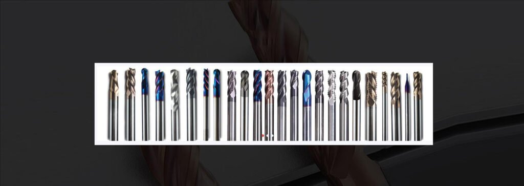
Furthermore, we recommend spiral flute taps for blind holes. A standard straight flute tap pushes chips forward. If you drill a blind hole based on the thread tap size chart and use a straight flute tap, the chips will pack into the bottom of the hole, ultimately snapping the tool. A spiral flute tap acts like an auger, pulling the swarf up and out of the hole, keeping the cutting edges clear and preventing catastrophic failure.
Frequently Asked Questions (FAQs)
Industry References
- International Organization for Standardization (ISO): ISO 529 Machine Taps Specifications.
- Deutsches Institut für Normung (DIN): DIN 371 and DIN 376 Standards for Threading Tools.
- Japanese Industrial Standards (JIS): JIS B 4430 Metric Machine Taps.
- MisolTap Engineering Data: 2026 Tolerance and Thread Engagement Guidelines.