
The collision between additive manufacturing and traditional subtractive machining is redefining industrial production. While 3D printing allows engineers to create impossibly complex geometries, it introduces severe complications when those parts need to interface with traditional mechanical fasteners. The way manufacturing (3D printing) affects thread tapping is entirely different from tapping a billet of cold-rolled steel or an injection-molded plastic housing. The internal structures, layer lines, thermal stresses, and surface roughness inherent to 3D printed components demand a complete paradigm shift in your tooling approach.
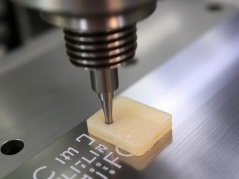
From our experience at MisolTap, producing cutting tools since 1991, we frequently see engineers attempting to CAD their threads and print them directly, only to watch them shear under load. We also see machinists destroying expensive taps on Direct Metal Laser Sintering (DMLS) parts because they treat the printed metal exactly like wrought stock. In this uncompromising guide, we will break down exactly how manufacturing (3D printing) affects thread tapping, expose the functional limitations of “as-printed” threads, and provide practical judgment on when you should tap, chase, or use inserts to secure your assemblies.
Quick Answer: Should You 3D Print Threads or Tap Them?
In most professional situations, we strongly advise against relying on directly 3D printed (“as-printed”) threads for functional, load-bearing applications. Additive manufacturing processes struggle with the minimum feature size required for thread crests and tapers, resulting in poor tolerance and weak engagement. We recommend printing a blank pilot hole at the exact tap drill size and cutting the threads post-build. For metal parts (DMLS/SLM), post-machining with a high-quality thread tap guarantees tight tolerances and proper alignment. For plastics (FDM, SLA, SLS), utilizing heat-set or press-fit threaded inserts provides vastly superior pull-out strength compared to tapping the plastic layers directly.
Table of Contents
- What It Is: The Intersection of AM and Machining
- How Manufacturing (3D Printing) Affects Thread Tapping
- The Benefits of Post-Build Tapping
- The Limitations of As-Printed Threads
- Who Should Use Tapping on 3D Parts
- Who Does Not Need It
- Common Mistakes in 3D Printed Threading
- Tooling Buying Considerations
- Comparison Table: Tapping vs. Inserts vs. Printed
- Pros and Cons of Metal AM Tapping
- Expert Recommendation from MisolTap
- Frequently Asked Questions (FAQ)
What It Is: The Intersection of AM and Machining
Understanding how manufacturing (3D printing) affects thread tapping begins with recognizing the fundamental difference in material structure. Additive Manufacturing (AM) builds parts layer by layer. Whether you are using Fused Deposition Modeling (FDM) to melt thermoplastics or Selective Laser Melting (SLM) to fuse metal powders, the resulting part is inherently anisotropic—meaning its physical properties differ depending on the direction of measurement.
Thread tapping is a subtractive process that relies on consistent material resistance to shear and cut chips smoothly. When a tap cuts into a 3D printed part, it interacts with layer boundaries, micro-porosities, and localized thermal hardening zones. Knowing the different types of thread taps is crucial because a standard hand tap designed for homogeneous steel will often catch on the layer lines of an AM part, causing aggressive tool wear or fracturing the printed component.
How Manufacturing (3D Printing) Affects Thread Tapping
The core issue of how manufacturing (3D printing) affects thread tapping comes down to the specific technology used to create the part. The approach you take for plastics will catastrophically fail on printed metals, and vice versa.
Tapping Metal AM Parts (DMLS, SLM)
Direct Metal Laser Sintering (DMLS) produces parts with a surface finish similar to sand casting. Furthermore, the rapid heating and cooling of the laser creates immense internal residual stresses. In our testing, attempting to tap “as-printed” holes in materials like Inconel 718 or Cobalt Chrome without proper preparation destroys cutting tools instantly. As-printed threads in metal rarely perform well due to severe material shrinkage and rough surface finishes. For the cleanest possible threads, the part must be printed with a blank hole, drilled to clear any distortion, and then tapped. Selecting the best material for thread taps—such as premium powdered metallurgy HSS-E or solid carbide—is non-negotiable for printed metals.
Tapping Plastic AM Parts (FDM, SLA, SLS)
Plastics present a different set of challenges. In FDM printing, holes printed horizontally tend to sag and flatten at the top. If you attempt to tap an out-of-round hole, the tap will bind. Moreover, tapping parallel to the Z-axis (between the layers) can cause the layers to delaminate and split under the radial pressure of the tap. For SLA thermoset resins, the material is highly brittle and can shatter if the tap drill size is too tight. Therefore, understanding how to properly use a thread tap with highly sensitive clutch settings is vital for plastic AM components.
The Benefits of Post-Build Tapping
For heavy-duty applications, taking the time to post-machine your 3D printed parts offers unparalleled mechanical advantages. When you print a pilot hole and tap it subtractively, you ensure perfect pitch diameter and thread engagement. This prevents cross-threading and fastener back-out during vibration.
Additionally, post-tapping allows for much tighter tolerancing. If your assembly requires an exact interference fit, you can use specialized cutting tools to achieve a Class 3B fit, which is physically impossible to 3D print directly due to the minimum feature size limits of the laser spot or extrusion nozzle.
The Limitations of As-Printed Threads
Many CAD engineers assume they can simply apply a cosmetic thread in SolidWorks, export the STL, and print a functional fastener. This is a myth. Threads with tapered edges lose definition when they become thinner than the printer’s minimum feature size. In some cases, the threads will not form at all, or the minor diameter will enlarge, creating a sloppy fit.
If you absolutely must print the threads directly into the model, we advise treating them merely as guide paths. You should then use the process of “thread chasing.” By running a tap through the pre-printed threads, you clean out the rough material. Learning the rethreading taps and dies methodology is highly effective for non-critical prototype parts where full machining setups are cost-prohibitive.
Who Should Use Tapping on 3D Parts
For commercial users and aerospace engineers: If you are manufacturing final end-use metal parts via DMLS or SLM, you must utilize post-build tapping. The functional demands of aerospace manifolds or automotive heat exchangers require perfect thread sealing. If you are dealing with blind holes in these expensive printed metals, understanding the plug tap vs thread tap dynamics will prevent bottoming out and breaking the tool inside a $5,000 prototype.
Who Does Not Need It
For beginners and hobbyist makers: If you are printing standard PLA, PETG, or ABS plastics on a desktop FDM machine, you generally do not need to tap the plastic. In most professional situations regarding plastics, installing heat-set brass inserts is vastly superior. These inserts are heated with a soldering iron and pressed into a blank printed hole, melting the plastic slightly so it grips the knurled exterior tightly. This provides incredible pull-out strength without the headache of matching cutting speeds and feeds.
Common Mistakes in 3D Printed Threading
The most catastrophic mistake in hybrid manufacturing is ignoring hole shrinkage. When a 3D printer creates an internal hole, the material tends to contract inward as it cools. A 5mm hole in CAD may print as 4.7mm. If you force an M5 tap into that undersized hole without reaming it to the correct tap drill size first, you will snap the tap. Always refer to a strict drilling speed for metal guide to clear the hole before tapping.
Another error is attempting to tap holes smaller than 0.5mm in metal AM parts. Holes this small are highly susceptible to distortion and closure during printing. You are better off printing a solid block and drilling the micro-hole entirely from scratch.
Tooling Buying Considerations
When selecting tooling for 3D printed parts, your primary concern must be chip evacuation and tool material. Printed metals are tough and abrasive. You require a heavy duty tap and drill combination specifically coated (like TiCN or TiAlN) to withstand the friction. Do not use generic carbon steel hand taps; they will fail on the first hole.
| Threading Method | Process Description | Best Material Application | Precision / Strength |
|---|---|---|---|
| Post-Build Tapping | Printing a blank hole, drilling to exact size, and tapping. | DMLS Metals, Tough SLA Resins | Highest Precision / High Strength |
| Heat-Set Inserts | Melting a brass threaded insert into an undersized printed hole. | FDM, SLS, MJF Thermoplastics | Moderate Precision / Highest Strength for Plastics |
| Thread Chasing | Printing the thread shape in CAD, then cleaning it with a tap. | Prototyping in Metal or Hard Plastics | Low Precision / Moderate Strength |
| As-Printed Threads | Using the 3D printer to directly form the final threads. | Large scale threads only (>M10) | Lowest Precision / Low Strength |
| Pros of Post-Tapping Metal Prints | Cons of Post-Tapping Metal Prints |
|---|---|
| Provides aerospace-grade thread engagement and sealing. | AM metals (like Inconel) cause rapid tool wear and high tap breakage risks. |
| Allows for tight Class 3B tolerances impossible to achieve by printing alone. | Requires an additional secondary machining setup, increasing lead time. |
| Eliminates the “stair-stepping” effect on thread flanks. | Blind holes are difficult to clear of chips due to rough internal printed walls. |
Expert Recommendation from MisolTap
The reality of how manufacturing (3D printing) affects thread tapping is that additive technology has not yet replaced subtractive precision. We definitively recommend that commercial users strip all threaded features from their 3D CAD models before sending them to the printer. Print solid material or undersized pilot holes, and rely on high-performance CNC tapping or thread milling to finish the job.
Your Trusted Partner in Threading Technology Since 1991
MisolTap (MisolGroup) has established itself as a leading manufacturer of high-performance thread cutting tools. We integrate R&D, production, and global sales into a seamless operation. As one of the top thread tap manufacturers, we understand the metallurgy required to cut through hardened 3D printed alloys.
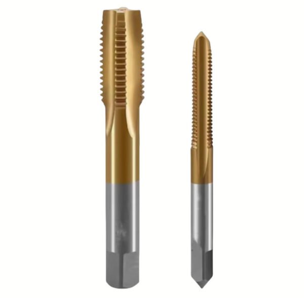
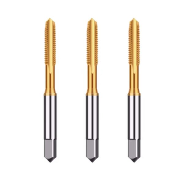
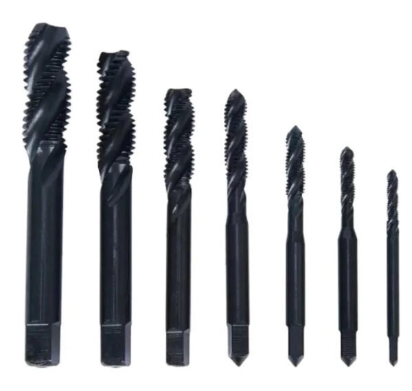
Our Capacity: With over 50 sets of 5-axis CNC grinding machines and in-house vacuum heat treatment, we ensure every tap meets the strictest tolerances. When you are machining expensive DMLS components, you cannot afford tool failure. Equip your shop with premium tooling engineered for the future of manufacturing.
Frequently Asked Questions (FAQ)
Can you 3D print threads directly without tapping?
Yes, but we strongly advise against it for functional or load-bearing parts. As-printed threads suffer from poor resolution, unpredictable material shrinkage, and rough surface finishes. The delicate tapered edges of threads often fail to print entirely because they fall below the minimum feature size limits of the 3D printer. For structural integrity, post-print tapping is essential.
Is it better to use threaded inserts or tap 3D printed plastic?
For 3D printed thermoplastics (like PLA, ABS, Nylon via FDM or SLS), using heat-set threaded inserts is vastly superior to tapping. Tapping directly into plastic layer lines creates very weak threads that will quickly strip out or cause the part to delaminate under stress. Heat-set inserts melt securely into the plastic, providing a robust, permanent metal thread interface.
Why do taps break easily when threading metal 3D printed parts?
Metal 3D printed parts (from DMLS or SLM processes) have incredibly rough, abrasive internal surfaces resembling cast metal. Furthermore, printed holes almost always shrink, leaving the pilot hole undersized. If a machinist forces a tap into this undersized, work-hardened hole without drilling it out to the exact tap drill specification first, the extreme torque and friction will instantly snap the cutting tool.
Authoritative Industry References
To ensure our machining guidelines and additive manufacturing analyses are empirically sound, we reference the following authoritative organizations:
- ASTM International: Specifically referencing ASTM F2792 – Standard Terminology for Additive Manufacturing Technologies, which defines the strict parameters and limitations of powder bed fusion and material extrusion processes. Review ASTM Standards
- Society of Manufacturing Engineers (SME): Utilizing peer-reviewed data on the machinability, tool wear, and surface finishing requirements for post-processing DMLS and SLM metal components. Explore SME Machining Resources
- Protolabs Engineering Guidelines: Industry-standard best practices for incorporating threaded features, inserts, and post-machining tolerances into industrial 3D printed models. Read Protolabs Threading Guidelines