
In the world of precision machining, measuring external threads is relatively straightforward. You can mic them, use thread wires, or throw them on an optical comparator. However, internal threads present a completely different logistical nightmare. You are dealing with blind holes, microscopic pitch diameters hidden from the naked eye, and complex helical geometries that standard calipers simply cannot reach. From our experience on the shop floor, assuming a tapped hole is “good enough” because the tap looked sharp is a fast track to catastrophic assembly failures, scrapped parts, and blown quality control audits.
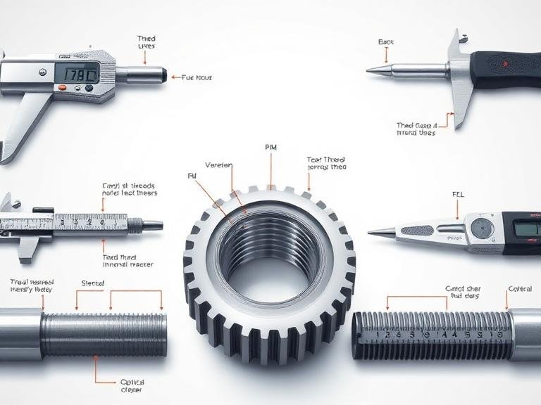
If you manufacture components for aerospace, medical, or heavy-duty automotive industries, understanding the definitive Methods for Measuring Internal Threads is not optional—it is a strict engineering mandate. You must move beyond rudimentary checks and utilize specialized metrology tools to guarantee pitch diameter, thread flank angle, and minor diameter tolerances are held. In this guide, we are breaking down the exact commercial and practical techniques you must employ, detailing not only what these methods are, but whether they actually make sense for your specific production environment.
Quick Answer: How to Measure Internal Threads
The most effective Methods for Measuring Internal Threads rely on checking the functional pitch diameter rather than just the minor diameter. The 7 primary methods are: 1) Go/No-Go Thread Plug Gauges (the industry standard for attribute checking), 2) Indicating Thread Gages (for variable, data-driven pitch diameter measurement), 3) Internal Thread Micrometers (using specialized V-anvils), 4) Casting/Molding Replicas (silicone impressions checked via optical comparator), 5) Coordinate Measuring Machines (CMM) (for ultimate high-end precision), 6) Air Gaging / Pneumatic Gauges (for rapid, high-volume production), and 7) The Master Mating Part Test (a rudimentary functional check). We recommend Go/No-Go gauges for fast production validation, and Indicating Gages or CMMs when SPC (Statistical Process Control) data is strictly required.
Table of Contents
- The Challenge of Internal Threads
- How It Works: The 7 Core Methods
- Benefits of Accurate Thread Measurement
- Limitations to Watch Out For
- Who Should Use Which Method
- Common Machining Mistakes
- Buying Considerations for Gauging Tools
- Summary & Comparison Tables
- Expert Recommendation from Misoltap
- Frequently Asked Questions (FAQ)
The Challenge of Internal Threads
Why are internal threads so difficult to measure? The answer lies in the geometry. A thread has three main diameters: the major diameter (the widest part, at the root of an internal thread), the minor diameter (the crest of the internal thread), and the pitch diameter (the theoretical midpoint where thread and groove widths are equal).
Standard calipers can only measure the minor diameter of an internal hole. But the minor diameter does not dictate the strength or fit of the bolt—the pitch diameter does. To accurately gauge the Methods for Measuring Internal Threads, your tools must be able to physically interface with the flanks (angled sides) of the thread inside a dark, often confined space. Whether you are using a standard plug tap vs thread tap, the tap cuts the pitch diameter, and that is exactly what your metrology tools must verify.
How It Works: The 7 Core Methods for Measuring Internal Threads
In most professional situations, you will rely on one or a combination of the following seven techniques to validate your tapped holes.
1. Go/No-Go Thread Plug Gauges (Attribute Gaging)
This is the undisputed workhorse of the machining industry. A thread plug gauge is a precision-ground, hardened steel tool with two ends. The “Go” end must thread completely into the hole without excessive force, verifying that the pitch diameter is not too small and the maximum material condition is met. The “No-Go” end is intentionally oversized and must NOT thread into the hole more than a couple of turns, verifying the pitch diameter is not too large. It is fast, operator-friendly, and definitively answers “is this part good or bad?”
2. Indicating Thread Gages (Variable Gaging)
While Go/No-Go gauges tell you if a part passes, they don’t tell you *where* it sits in the tolerance band. Indicating thread gages use internal expanding segments or rolls connected to a dial indicator. You insert the gage, squeeze the trigger, and the segments expand into the thread flanks. It provides an exact numeric value of the pitch diameter. This method is mandatory if you are tracking tool wear or compiling Statistical Process Control (SPC) data.
3. Internal Thread Micrometers
Similar to standard inside micrometers, these tools feature interchangeable V-shaped and cone-shaped anvils designed to seat perfectly within the flank angles of the thread. They provide a direct, variable measurement of the pitch diameter. They require more operator skill than an indicating gage and are notoriously difficult to use on small-diameter holes, but they are highly versatile for job shops dealing with custom 1/2 thread tap size chart variations.
4. Casting / Molding Replicas
When you cannot see inside a deep blind hole to verify the root radius or flank angle, you must bring the thread outside. By injecting a specialized metrology-grade silicone or resin (like ReproRubber) into the hole, letting it cure, and unthreading the flexible mold, you create a perfect replica of the internal thread. You then place this replica on an optical comparator to measure the profile visually. It is slow but invaluable for aerospace quality audits.
5. Coordinate Measuring Machines (CMM)
For heavy-duty applications where sub-micron accuracy is required, a CMM is deployed. Advanced CMMs use a tactile ruby probe that drives into the hole and traces the helical path of the thread, digitally mapping the pitch diameter, major diameter, lead, and flank angle simultaneously. It is the ultimate authority in metrology, but requires massive capital investment and programming time.
6. Pneumatic Gauging (Air Gaging)
In ultra-high-volume automotive manufacturing, threading a plug gauge into 5,000 engine blocks a day is too slow. Air gaging uses a specialized threaded plug that shoots compressed air against the internal flanks of the thread. The system measures the backpressure to calculate the exact size of the pitch diameter. It is contactless, highly accurate, and incredibly fast.
7. The Master Mating Part Test
This is the most basic, functional form of the Methods for Measuring Internal Threads. It involves taking a known, certified master bolt and threading it into the hole by hand to feel for binding, slop, or cross-threading. While it lacks numerical data and cannot isolate specific geometric errors (like pitch deviation), it is a pragmatic final sanity check often used by beginners or in low-stakes structural fabrication.
Benefits of Accurate Thread Measurement
The primary benefit of utilizing rigorous Methods for Measuring Internal Threads is the absolute elimination of assembly failures. A bolt that strips out of an engine block because the internal pitch diameter was machined too large costs thousands of dollars to repair via helicoils or part scrapping. By investing in proper metrology, you validate that your chosen din371 thread tap supplier provided tooling that cuts to the exact tolerance class (e.g., 6H or 2B) required by the blueprint.
Limitations to Watch Out For
We must use commercial and practical judgment: variable gaging (like CMMs and Indicating Gages) is slow and expensive. Furthermore, Go/No-Go gauges are subject to mechanical wear. If you use a steel plug gauge to check thousands of holes in abrasive cast iron, the “Go” gauge will eventually wear down, causing it to accept undersized threads. You must manage gauge calibration schedules relentlessly.
Who Should Use Which Method & Who Doesn’t Need It
For commercial users and high-volume machine shops: We recommend a dual-pronged approach. Use Indicating Thread Gages to set up the machine and monitor tap wear, and equip your operators with calibrated Go/No-Go thread plug gauges for 100% attribute inspection on the line.
Who does not need it: For basic maintenance, hobbyist fabrication, or chasing dirty threads with rethreading taps and dies, investing $2,000 in an indicating gage is overkill. A standard thread plug gauge or a high-quality mating bolt is sufficient to verify the repair.
Common Machining Mistakes
The most catastrophic mistake operators make is believing that a properly sized tap drill guarantees a perfect thread. If you reference a tap and drill size chart and drill the hole perfectly, but use a worn-out tap or experience spindle runout, your pitch diameter will cut oversized.
Another profound error is attempting to evaluate the Methods for Measuring Internal Threads using standard jaw calipers on the minor diameter. The minor diameter tells you the size of the pre-drilled hole; it tells you absolutely nothing about the depth or accuracy of the V-threads cut into the wall. Always follow the fundamental rules of how to tap threads in metal by validating the pitch line.
Buying Considerations for Gauging Tools
When purchasing thread gauges, you must specify the exact Class of Fit. An M10x1.5 6H plug gauge is dimensionally different from an M10x1.5 6G plug gauge. Furthermore, evaluate your tool life. If you are machining highly abrasive materials, consider buying TiN-coated or solid carbide Go/No-Go gauges, as standard hardened steel gauges will wear out prematurely.
Essential Measurement & Comparison Tables
| Measurement Method | Data Type | Best Industrial Application |
|---|---|---|
| Go/No-Go Plug Gauge | Attribute (Pass/Fail) | Fast, high-volume production line inspection. |
| Indicating Thread Gage | Variable (Numeric) | Machine setup, SPC data tracking, tool wear monitoring. |
| Internal Micrometer | Variable (Numeric) | Low-volume, custom job shops requiring flexibility. |
| CMM / Tactile Scan | Comprehensive Digital | Aerospace validation, first-article inspection. |
| Feature | Go/No-Go Plug Gauge | Indicating Thread Gage |
|---|---|---|
| Initial Cost | Low ($50 – $150) | High ($1,000+) |
| Speed of Inspection | Very Fast | Moderate |
| Operator Skill Required | Low (Requires basic feel) | Medium (Requires seating and dial reading) |
| Detects Taper/Ovality? | No (Only checks max/min material condition) | Yes (Identifies out-of-round conditions) |
| The Pros (Advantages) | The Cons (Disadvantages) |
|---|---|
| Allows visual inspection of blind hole root radii. | Extremely slow process (requires cure time). |
| Reveals tearing or galling on the thread flanks. | Requires secondary equipment (Optical Comparator). |
| Highly accurate for complex, non-standard thread profiles. | Molding compound is a consumable, recurring cost. |
Expert Recommendation from Misoltap
In most professional situations, the accuracy of your internal threads is entirely dependent on the quality of the cutting tool you drive into the hole. Understanding the Methods for Measuring Internal Threads is critical, but if you start with an inferior tap, you will spend all day rejecting parts. You must evaluate the best material for thread taps based on your workpiece to ensure geometric stability.
We recommend combining rigid machine tapping protocols with elite cutting geometry. For blind holes and precise pitch control, you need a tap designed for optimal chip evacuation.
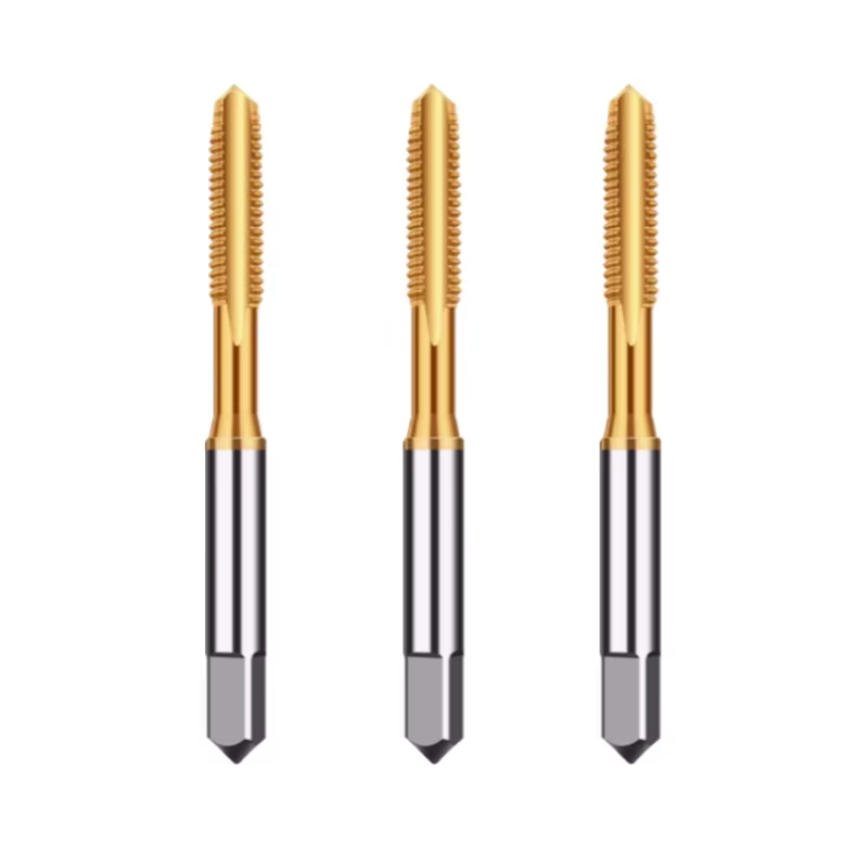
MSL002 Straight Flute Thread Tap
Engineered for exacting tolerances, this tap is the foundation for cutting internal threads that pass Go/No-Go gauge inspections on the first pass.
- Thread Size (M3*0.35): This tap is designed specifically for M3*0.35 threaded holes, providing precision and accuracy in all applications.
- Length (48mm): A compact design suitable for various threading depths.
- Thread Length (11mm): Ensures optimal threading performance and flank engagement.
- Neck Length (7mm): Improves chip removal, keeping the threading process smooth and preventing pitch diameter tearing.
- Handle Length (3.15mm): Features a rough handle for improved grip and control during operation.
- Square Type FE (2.55): Provides a secure fit for enhanced machine performance.
By upgrading to precision-ground taps like the MSL002 and understanding the dynamic machine tap vs hand tap applications, your quality control department will spend less time rejecting parts and more time approving production batches.
Frequently Asked Questions (FAQ)
Why shouldn’t I just use a digital caliper to measure an internal thread?
A standard digital caliper can only measure the minor diameter (the crest of the internal threads). It physically cannot reach the pitch diameter or the root of the thread, which are the critical dimensions determining thread strength and fit. Relying on calipers for internal threads guarantees inaccurate quality control.
How often should Go/No-Go thread plug gauges be calibrated?
In high-volume commercial applications, thread plug gauges should be verified against a master setting ring or sent for independent calibration every 3 to 6 months. Frequent use wears down the gauge’s pitch diameter, causing it to accept out-of-tolerance parts if not actively monitored.
What is the pitch diameter and why is it important?
The pitch diameter is an imaginary cylinder where the width of the thread and the width of the groove are exactly equal. It is the most critical dimension of any thread because it dictates how the internal and external threads mate, directly affecting the shear strength and vibration resistance of the joint.
Authoritative Industry References
To ensure your metrology department adheres to the highest global standards for thread verification, we strongly advise consulting the following engineering bodies:
- American Society of Mechanical Engineers (ASME) – ASME B1.2 standard defines the precise specifications and calibration requirements for gages and gaging for unified inch screw threads.
- International Organization for Standardization (ISO) – ISO 1502 provides the foundational international standards for general-purpose metric screw threads, specifically regarding gauges and gauging techniques.
- National Institute of Standards and Technology (NIST) – Offers definitive metrology frameworks and calibration traceability protocols vital for ensuring aerospace and medical manufacturing accuracy.