
Achieving flawless internal threads in industrial machining requires an uncompromising approach to cutting parameters. In high-volume B2B manufacturing, poor cycle times and broken tools severely impact profit margins. Unlike standard milling or turning operations, establishing the correct Thread tapping speed and feed leaves virtually zero room for error. The tap must advance precisely one thread pitch per revolution. Any deviation from this synchronized mechanical movement results in stripped threads, damaged components, or catastrophic tool failure within the spindle.
Since our founding in 2005, MisolTap has established itself as a leading Chinese manufacturer of high-performance thread cutting tools. We integrate R&D, production, and global sales into a seamless operation, providing our clients with robust and precise threading solutions tailored to modern manufacturing needs. From our experience collaborating with aerospace, automotive, and heavy industry machining centers, optimizing Thread tapping speed and feed parameters is the single most critical factor in maximizing tool life. This authoritative guide details the engineering formulas, material considerations, and practical strategies required to execute perfect threading operations.
Table of Contents
- 1. The Physics of Thread Tapping Speed and Feed
- 2. Calculating Exact Thread Tapping Speed and Feed Rates
- 3. Material Considerations and Machinability
- 4. Tooling Selection and Manufacturer Impact
- 5. Unique Parameters for Pipe Threads
- 6. Summary Table: Recommended Thread Tapping Speed and Feed Parameters
- 7. Troubleshooting Thread Tapping Speed and Feed Errors
- 8. Frequently Asked Questions (FAQs)
- 9. Academic and Industry References
1. The Physics of Thread Tapping Speed and Feed
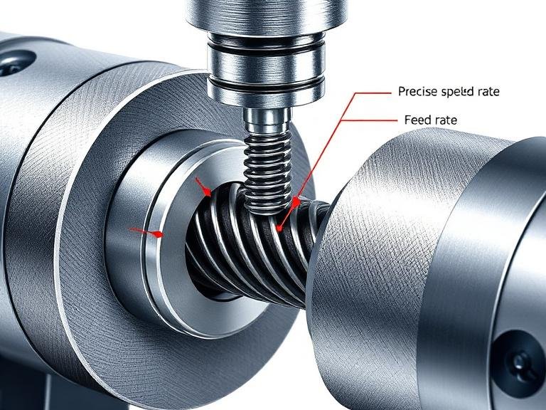
To master the Thread tapping speed and feed dynamic, CNC programmers and machinists must understand the rigid relationship between the tool’s rotation and its linear advancement. In milling, a machinist can adjust the feed rate independently of the spindle speed to alter chip thickness. In tapping, the feed rate is mathematically locked to the spindle speed by the pitch of the thread. For every single rotation of the spindle, the Z-axis must feed exactly the distance of one thread pitch.
This synchronization requires specialized equipment and careful programming. Modern CNC machines utilize rigid tapping cycles (G84 in standard G-code), which electronically synchronize the spindle encoder with the Z-axis servomotor. If your workshop operates older equipment without rigid tapping capabilities, we recommend utilizing a tension-compression floating tap holder. This mechanical device provides a small amount of axial float, compensating for any minor discrepancies in the Thread tapping speed and feed synchronization and preventing the tap from snapping during reversal.
Furthermore, proper hole preparation directly dictates tapping success. Establishing the correct core hole diameter determines the percentage of thread engagement. Before configuring your Thread tapping speed and feed, it is vital to optimize your pre-drill parameters. A thorough understanding of the optimal drilling speed for metal ensures that the core hole is perfectly cylindrical and free of work-hardening, which drastically reduces the torque load on the tap.
2. Calculating Exact Thread Tapping Speed and Feed Rates
Calculating the correct Thread tapping speed and feed begins with determining the ideal Surface Feet per Minute (SFM) for the material you are machining. SFM represents the speed at which the cutting edge of the tap moves through the material. Once the SFM is selected from tooling data charts, you calculate the Spindle RPM, and subsequently, the Feed Rate in Inches Per Minute (IPM) or Millimeters Per Minute (mm/min).
The standard formula for calculating RPM in imperial units is: RPM = (SFM x 3.82) / Tap Diameter.
Once the RPM is established, the feed rate calculation ensures the tool advances correctly. For unified threads (TPI), the feed rate formula is: Feed (IPM) = RPM / TPI. For metric threads, the formula converts to: Feed (mm/min) = RPM x Pitch (mm).
For example, if you are tapping a 1/4-20 thread in low carbon steel with an SFM of 40:
RPM = (40 x 3.82) / 0.250 = 611 RPM.
Feed Rate = 611 / 20 = 30.55 IPM.
By strictly adhering to these calculations, you ensure that your Thread tapping speed and feed perfectly match the mechanical geometry of the tool, minimizing axial thrust forces.
3. Material Considerations and Machinability
The selection of Thread tapping speed and feed parameters is heavily influenced by the metallurgical properties of the workpiece. Different alloys exhibit varying levels of hardness, ductility, and thermal conductivity, all of which alter the cutting environment at the tap’s cutting edge.
When machining soft, non-ferrous materials like 6061 aluminum or brass, machinists can employ aggressive Thread tapping speed and feed rates. High spindle speeds prevent the soft material from welding to the tap’s flutes, a phenomenon known as built-up edge (BUE). Conversely, high-tensile materials such as 304 stainless steel, titanium, or Inconel require significantly reduced SFM to manage the intense heat generated during the cutting process. Excessive speed in these alloys will instantly burn the cutting edges and cause catastrophic tool failure.
For operations involving deep-hole tapping in robust forgings or castings, tool rigidity becomes paramount. Selecting the right geometry and coating is just as critical as the programmed speeds. Engineers handling large-scale structural components should review comprehensive options for a heavy duty tap and drill setup to ensure the tooling can withstand high torque thresholds without shearing under extreme loads.
4. Tooling Selection and Manufacturer Impact
The baseline capabilities of your Thread tapping speed and feed are largely determined by the quality and substrate of the tap itself. High-Speed Steel (HSS) taps are the industry standard for general-purpose machining, offering excellent toughness and resistance to chipping. However, advanced Powdered Metal (PM) and solid carbide taps allow workshops to push Thread tapping speed and feed rates up to three times faster than standard HSS tools, significantly reducing cycle times in high-volume production runs.
Since 2005, MisolTap has invested heavily in coating technologies. Applying Physical Vapor Deposition (PVD) coatings such as Titanium Nitride (TiN), Titanium Carbonitride (TiCN), or Titanium Aluminum Nitride (TiAlN) enhances surface hardness and reduces friction. We recommend utilizing TiAlN coated taps for high-heat applications, as the coating forms a protective aluminum oxide layer at elevated temperatures, allowing for aggressive Thread tapping speed and feed parameters in tough aerospace alloys.
Selecting a reliable supply chain partner is critical for maintaining consistency on the shop floor. Sourcing tools from top-tier thread tap manufacturers guarantees that the tools conform to strict dimensional tolerances, ensuring repeatable performance across thousands of holes. Furthermore, specialized applications occasionally require non-standard tooling, such as reverse thread taps for rotating assemblies. These left-hand thread tools require identical Thread tapping speed and feed calculations but demand careful spindle rotation programming (M04 instead of M03 in G-code).
5. Unique Parameters for Pipe Threads
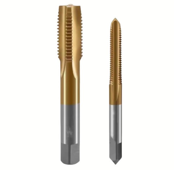
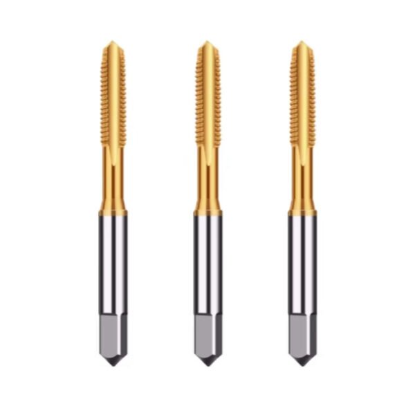
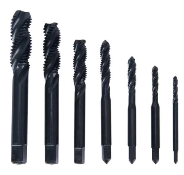
Tapping tapered pipe threads, such as NPT (National Pipe Taper) or BSPT (British Standard Pipe Taper), presents unique challenges for Thread tapping speed and feed configurations. Unlike straight machine threads, a tapered tap engages more material with every single revolution as it descends into the hole. By the time the tap reaches its final depth, the entire length of the tool is cutting simultaneously, generating immense torque and radial pressure.
From our experience, we recommend reducing your calculated Thread tapping speed and feed by approximately 25% to 40% when transitioning from straight threads to tapered pipe threads in the same material. This reduction in RPM mitigates heat buildup and prevents the tap from binding or stalling the machine spindle. Proper sizing of the pre-drill is even more critical here; utilizing a taper reamer before tapping can drastically improve tool life. For exact pre-drill dimensions, referencing a precise pipe thread tap size chart is mandatory.
When working with common industrial fluid power ports, such as pneumatics or hydraulics, machinists frequently encounter specific dimensional requirements. Understanding the core hole and engagement depth for specific tools, such as the 3/8 pipe thread tap size, ensures leak-free joints and prevents the severe galling associated with incorrect Thread tapping speed and feed implementation.
6. Summary Table: Recommended Thread Tapping Speed and Feed Parameters
To assist CNC programmers and manufacturing engineers, we have compiled a baseline reference matrix. Please note that these Thread tapping speed and feed values are starting points for coated HSS-E (Cobalt) taps and should be adjusted based on machine rigidity, coolant concentration, and specific alloy variations.
| Workpiece Material | Hardness (Brinell) | Recommended Cutting Speed (SFM) | Recommended Cutting Speed (m/min) | Thread Tapping Speed and Feed Notes |
|---|---|---|---|---|
| Aluminum Alloys (6061, 7075) | 30 – 150 HB | 80 – 150 SFM | 24 – 45 m/min | Use high speeds to prevent built-up edge; high lubricity coolant required. |
| Low Carbon Steel (1018, A36) | 100 – 150 HB | 40 – 60 SFM | 12 – 18 m/min | Excellent chip formation; standard rigid tapping speeds apply. |
| Medium Carbon & Alloy Steel (4140) | 200 – 300 HB | 25 – 40 SFM | 8 – 12 m/min | Reduce speed for heat treated states; TiCN coating recommended. |
| Stainless Steel (304, 316) | 150 – 250 HB | 15 – 30 SFM | 5 – 9 m/min | Highly susceptible to work hardening; maintain steady, uninterrupted feed. |
| Titanium & Exotic Superalloys | 250 – 400 HB | 10 – 20 SFM | 3 – 6 m/min | Extreme heat generation; use lowest Thread tapping speed and feed; specialized lubricants needed. |
| Cast Iron (Gray & Ductile) | 150 – 250 HB | 40 – 70 SFM | 12 – 21 m/min | Produces abrasive, powdery chips; TiAlN coating performs best. |
7. Troubleshooting Thread Tapping Speed and Feed Errors
Even with rigorous calculations, real-world machining environments introduce variables that can disrupt the Thread tapping speed and feed balance. Identifying the root cause of poor thread quality or tool breakage is an essential skill for B2B workshop managers.
From our experience, if a tap breaks upon reversal (backing out of the hole), the primary culprit is often a lack of spindle synchronization or packed chips at the bottom of a blind hole. If your Thread tapping speed and feed are mathematically correct, verify that the coolant concentration is sufficient (typically 8% to 12% for tapping) to flush chips out of the flutes. Conversely, if the finished threads gauge oversized or exhibit torn flanks, the spindle RPM may be too low, causing the tap to push and tear the material rather than shearing it cleanly. In materials like stainless steel, insufficient Thread tapping speed and feed rates lead to work-hardening, destroying the tap’s chamfer on subsequent holes.
8. Frequently Asked Questions (FAQs)
How does rigid tapping differ from standard tapping regarding Thread tapping speed and feed?
Rigid tapping utilizes electronic feedback between the CNC spindle and the Z-axis servo to perfectly synchronize rotation and linear feed. This eliminates the need for mechanical tension-compression holders, allowing for faster Thread tapping speed and feed rates and ensuring exact depth control in blind holes.
Can I use the same Thread tapping speed and feed for both cut taps and roll (form) taps?
No. We recommend operating roll (form) taps at Thread tapping speed and feed rates approximately 50% to 100% faster than standard cutting taps. Form taps do not produce chips; they displace material through friction and pressure. Higher spindle speeds generate the necessary heat to plasticize the metal, forming a stronger thread profile.
What is the most common sign that my Thread tapping speed and feed are set too high?
The most immediate indicator of excessive Thread tapping speed and feed is rapid tool wear on the chamfered cutting edges, often accompanied by discoloration (bluing) of the tap due to extreme heat. You may also hear high-pitched squealing during the cutting cycle, followed shortly by complete tool breakage.
How does coolant affect my selected Thread tapping speed and feed?
Coolant provides both temperature reduction and lubricity. When machining gummy materials like aluminum or tough alloys like stainless steel, high-pressure, high-concentration coolant prevents chips from welding to the tool. Proper lubrication allows you to optimize your Thread tapping speed and feed at the higher end of the manufacturer’s recommended spectrum.
9. Academic and Industry References
To ensure precision and compliance with global manufacturing standards, the engineering formulas and machinability data referenced in this guide align with the following authoritative bodies:
- National Institute of Standards and Technology (NIST) – Advanced Machining and Manufacturing Metrology Guidelines.
- International Organization for Standardization (ISO) – ISO 5969:1979 Ground thread taps for ISO metric threads — Tolerances on the threaded portion.
- Society of Manufacturing Engineers (SME) – Tool and Manufacturing Engineers Handbook (TMEH), Machining Volume.