
Let us be brutally honest: if you are guessing your hole sizes on the shop floor, you are throwing money away. In modern manufacturing, snapping a high-speed steel tap inside a nearly finished titanium or stainless steel aerospace component is an unforgivable error. It destroys tooling, halts production lines, and forces machinists into hours of tedious EDM extraction. The root cause of this failure is almost always an improperly sized pre-drilled hole. To protect your workpieces and your profit margins, you must know exactly how to calculate tap drill size for metric threads.

From our experience engineering precision cutting tools, blindly trusting a generic poster taped to a workshop wall is dangerous. Different materials, different thread percentage requirements, and different tapping methods (cut tapping versus form tapping) demand completely different mathematical approaches. In this comprehensive guide, we strip away the guesswork. We will break down the eight proven methods professionals use to determine the exact drill diameter required for flawless metric threading, ensuring you make the right tooling decisions before the spindle ever turns.
Quick Answer: The Standard Metric Calculation
In most professional situations, the fastest and most universally accepted way to calculate tap drill size for metric threads is to subtract the thread pitch from the nominal major diameter. The formula is: Major Diameter – Pitch = Tap Drill Size. For example, if you are machining an M8 x 1.25 thread, the math is 8.0 – 1.25, meaning you must use a 6.75mm drill bit. This straightforward calculation yields approximately 75% thread engagement, which is the industry standard for general-purpose fastening.
Table of Contents
- What It Is: The Physics of Tapping
- How It Works: 8 Ways to Calculate Tap Drill Size for Metric Threads
- The Commercial Benefits of Precision Sizing
- Limitations and Mechanical Realities
- Who Should Use It & Who Does Not Need It
- Common Machining Mistakes
- Buying Considerations for Tooling
- Expert Recommendation
- Frequently Asked Questions (FAQ)
What It Is: The Physics of Tapping
A tap drill size is the specific diameter of a hole that must be bored into a material before an internal thread can be cut or formed. If you drill the hole too small, the volume of material left behind is too dense for the tap to displace or cut; the torque forces will compound until the tap shatters. If you drill the hole too large, the tap will cut shallow, truncated threads. When a bolt is inserted and torqued down, those shallow threads will instantly strip out.
When we talk about how to calculate tap drill size for metric threads, we are ultimately managing thread engagement percentage. A 100% thread engagement requires massive torque and provides virtually no additional strength over a 75% thread engagement. Therefore, the goal of these calculations is to leave just enough material in the hole to form a structurally sound thread profile without destroying your tooling.
How It Works: 8 Ways to Calculate Tap Drill Size for Metric Threads
Depending on your application, your material, and the type of tap you are using, you must select the appropriate methodology. Here are the eight expert methods to determine your drill size.
1. The Standard Pitch Subtraction (The 75% Rule)
As mentioned in our quick answer, this is the bedrock formula for cut taps. By taking the major diameter (the ‘M’ number) and subtracting the pitch, you arrive at a drill size that provides roughly 75% to 77% thread engagement. It is fast, mental math that works flawlessly for standard steels and alloys.
- Example: M10 x 1.50 -> 10 – 1.50 = 8.5mm drill bit.
2. The Precise Thread Percentage Formula
For heavy-duty applications where engineering prints demand a specific thread engagement (e.g., 60% for hard materials like Inconel to prevent tap breakage, or 80% for soft plastics to prevent stripping), you must use the advanced formula. The formula is: Drill Size = Major Diameter – ((Pitch x 0.6495) x (Desired Thread % / 100) x 2). This allows CNC programmers to dial in the exact hole diameter required to balance tool life with holding power.
3. The Form Tapping Calculation
We recommend paying close attention here: form taps (also known as roll taps or fluteless taps) do not cut material; they cold-forge it. They displace the metal, pushing it into the thread crests. Therefore, form tapping requires a significantly larger pre-drilled hole. The formula for metric form taps is: Major Diameter – (Pitch / 2) = Drill Size.
- Example: M8 x 1.25 Form Tap -> 8.0 – (1.25 / 2) = 7.375mm (typically rounded to a 7.4mm drill).
4. Utilizing an ISO Standardized Wall Chart
While math is essential, referencing an official tap and drill size chart is the fastest workflow in a production environment. However, you must ensure your chart clearly distinguishes between cut taps and form taps, as confusing the two will result in immediate part failure.
5. Material-Specific Adjustments
Calculations assume the material behaves perfectly. In reality, materials like copper, brass, and certain plastics experience “spring-back” after drilling. If you drill a 5.0mm hole in a resilient plastic, the hole may shrink to 4.95mm when the drill retracts. In our testing, when tapping highly elastic or tough materials, you must calculate the standard size and then step up to the next available drill diameter (e.g., adding 0.1mm) to prevent tap binding.
6. The Fine Pitch Approximation
When dealing with metric fine threads (e.g., M12 x 1.25 instead of the standard M12 x 1.75), the volume of material removed by the tap is drastically smaller. The standard subtraction rule still applies perfectly, but because the pitch is so shallow, you can often afford to increase the thread engagement to 80% without risking tap breakage, resulting in a superior seal for hydraulic fittings.
7. Using Dedicated Machining Software
In modern CNC environments, operators do not use calculators; they use CAM software or dedicated machining apps. Programs from leading tooling manufacturers allow you to input the M-size, pitch, material hardness, and desired thread percentage, and the software instantly outputs the exact drill size required to achieve the optimum chip load.
8. Reverse Engineering with Thread Gauges
If you are repairing machinery and encounter an unknown metric thread, you must first identify the pitch using a thread pitch gauge. Once the pitch is verified and the major diameter is calipered, you can retroactively apply the standard subtraction formula to figure out what drill size the original manufacturer used. This is critical when utilizing rethreading taps and dies to repair damaged engine blocks.
The Commercial Benefits of Precision Sizing
In most professional situations, the benefits of taking the time to calculate tap drill size for metric threads accurately translate directly to the bottom line. Accurate sizing extends the lifespan of your threading taps by reducing radial torque. It drastically lowers your scrap rate by eliminating broken tools lodged in expensive workpieces. Furthermore, it ensures that your assemblies pass rigorous quality assurance torque tests, guaranteeing that bolts will not pull out of the threads under dynamic loads.
Limitations and Mechanical Realities
Math on paper has limitations on the shop floor. The primary limitation is drill runout. If your calculation dictates a 6.8mm drill bit, but your drill press spindle has terrible runout, the drill bit will wobble and cut a 6.9mm or 7.0mm hole. The math was correct, but the mechanical execution failed, resulting in oversized, weak threads. You must ensure your drilling equipment is rigid and true before executing how to tap threads in metal protocols.
| Method | Formula / Action | Best Used For |
|---|---|---|
| Standard Cut Tapping | Major Dia – Pitch | Everyday shop use; standard 75% thread engagement. |
| Form (Roll) Tapping | Major Dia – (Pitch / 2) | Ductile materials like aluminum; stronger thread profiles. |
| Custom Engagement % | Major Dia – ((Pitch x 0.6495) x (% / 100) x 2) | Aerospace, hardened alloys, titanium machining. |
Who Should Use It & Who Does Not Need It
For commercial users and CNC machinists: Understanding these calculations is non-negotiable. Whether you are running a production line of automotive parts or fabricating custom robotics, you must know how to manipulate drill sizes to manage tool wear and part integrity. If you are operating automated equipment, understanding the machine tap vs hand tap dynamics alongside these calculations dictates your feed and speed rates.
Who does not need it: Casual hobbyists working exclusively with wood or very soft plastics. In these materials, threading tolerances are incredibly forgiving, and self-tapping wood screws largely eliminate the need for precision metric thread calculations.
Common Machining Mistakes
The most egregious error we witness is machinists attempting to substitute fractional imperial drill bits for exact metric sizes. Do not use a 1/4″ drill bit (6.35mm) when an M8 x 1.25 demands a 6.75mm hole. The tap will violently bind and shatter. You must invest in a comprehensive metric drill index.
Another common mistake is failing to clear chips in blind holes. Even if your calculation is perfect, if you do not understand how to use a thread tap properly—by backing off every half-turn to break the chip—the compressed swarf at the bottom of the hole will destroy the tool.
| Metric Thread Size | Cut Tap Drill Size (Subtract Pitch) | Form Tap Drill Size (Subtract Half Pitch) |
|---|---|---|
| M4 x 0.70 | 3.30 mm | 3.65 mm |
| M6 x 1.00 | 5.00 mm | 5.50 mm |
| M10 x 1.50 | 8.50 mm | 9.25 mm |
Buying Considerations for Tooling
When you calculate tap drill size for metric threads, you must also secure the corresponding hardware. Buying cheap, unbranded carbon steel drill bits will ruin your tolerances. You must source HSS-Co (Cobalt) or solid carbide drill bits to ensure hole dimensional stability. Furthermore, selecting the best material for thread taps—such as powder metallurgy high-speed steel (PM-HSS) with TiCN coatings—will guarantee that your tap survives the rigors of commercial production.
| Tool Component | Recommendation | Why It Matters |
|---|---|---|
| Drill Bits | 135-degree Split Point Cobalt (HSS-Co) | Prevents walking on hard surfaces, ensuring perfect hole concentricity. |
| Blind Hole Taps | Spiral Flute Taps | Draws chips upward and out of the hole, preventing bottom-out breakage. |
| Through Hole Taps | Spiral Point (Gun) Taps | Pushes chips forward ahead of the cutting action for high-speed tapping. |
Expert Recommendation from MisolTap
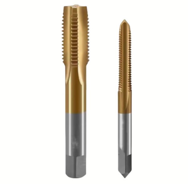
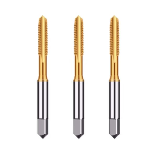
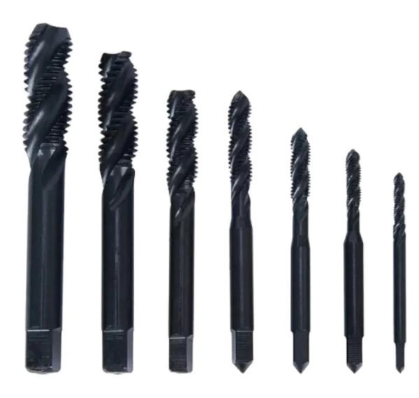
In most professional situations, calculating the precise drill size is only 50% of the battle; the other 50% is the quality of the tooling you deploy. Whether you are seeking a standard din371 thread tap supplier or evaluating the nuances of a plug tap vs thread tap, compromising on quality leads to catastrophic manufacturing delays.
Since our founding in 2005, MisolTap has established itself as a leading Chinese manufacturer of high-performance thread cutting tools. We integrate R&D, production, and global sales into a seamless operation, providing our clients with robust and precise threading solutions tailored to modern manufacturing needs. We recommend always verifying your math, maintaining strict machine rigidity, and partnering with a premium tooling provider to ensure your threads perform flawlessly under pressure.
Frequently Asked Questions (FAQ)
How do you calculate tap drill size for metric threads manually?
To calculate tap drill size for metric threads, you subtract the thread pitch from the major diameter. For example, for an M10 x 1.5 thread, you subtract 1.5 from 10, resulting in an 8.5mm drill bit requirement.
Can I use fractional inch drill bits for metric taps?
From our experience, using fractional inch drill bits for metric taps is a massive operational mistake. The tolerances rarely align perfectly, resulting in either a hole that is too tight (causing tap breakage) or a hole that is too loose (causing thread stripping under load).
Why did my tap break even if my drill size calculation was correct?
Even with perfect math, a tap will break if chip evacuation is poor, lubrication is insufficient, or if drill runout caused the hole to become work-hardened or misaligned prior to the tapping operation.
Authoritative References
To ensure absolute compliance with global manufacturing and engineering standards, we recommend consulting the following organizations for standardized threading metrics and tolerances:
- International Organization for Standardization (ISO) – Governing body defining universal metric thread profiles, pitch data, and manufacturing tolerances.
- American Society of Mechanical Engineers (ASME) – Providing comprehensive codes and standards for mechanical engineering, threading standards, and fastener integrity.
- Cutting Tool Engineering (CTE) – A premier industry publication offering advanced insights into modern machining strategies, tooling metallurgy, and high-performance tapping techniques.