
In modern manufacturing and metal fabrication, the failure to understand fundamental hole dynamics is a fast track to scrapped parts, broken tooling, and compromised structural assemblies. When you need to bolt two pieces of metal together, you do not just drill a single uniform hole through both plates. That is an amateur mistake that leads to thread binding and zero clamping force. To achieve a functional bolted joint, you must utilize two distinctly different hole preparation strategies on the mating components.
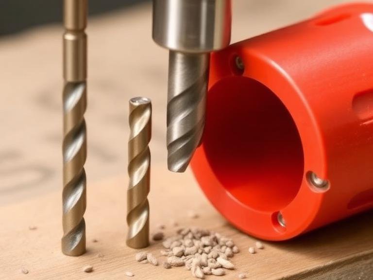
From our experience on the shop floor and in the engineering lab, miscalculating the nuances between a tap drill size and clearance hole size is the number one cause of fastener failure. In most professional situations, precision is not a suggestion; it is the absolute baseline. If you drill your tap hole too large, your threads will strip out under load. If you drill your clearance hole too small, your bolt will jam before it ever seats. This comprehensive guide breaks down exactly what separates these two critical machining operations, how to calculate them accurately, and how to select the right tooling to execute them without destroying your workpiece.
Quick Answer: Tap Drill Size and Clearance Hole Size Explained
The primary difference between a tap drill size and clearance hole size lies in their functional relationship to the fastener. A tap drill size is strictly smaller than the major diameter of the screw; it removes just enough material to allow a threading tap to enter and cut internal threads into the remaining metal walls. Conversely, a clearance hole size is strictly larger than the major diameter of the screw; it is completely unthreaded, allowing the fastener’s shaft to pass through freely without any binding or rotation resistance, ensuring the bolt head can compress the two mating parts together.
Table of Contents
- What They Are: Defining the Tooling Functions
- How It Works: The Mechanics of a Bolted Joint
- The 7 Core Differences Explained
- Comparison Table: Tap Drill vs. Clearance Hole
- Benefits of Precise Hole Sizing
- Limitations and Mechanical Risks
- Who Should Use It & Who Does Not Need It
- Common Machining Mistakes to Avoid
- Buying Considerations for Industrial Tooling
- Expert Recommendation from MisolTap
- Frequently Asked Questions (FAQ)
What They Are: Defining the Tooling Functions
Before you load a drill bit into your CNC spindle or drill press, you must understand the mechanical intent of the hole. A tap drill prepares a blind or through-hole to receive a specific tap. It is mathematically calculated to yield a specific percentage of thread engagement—typically 75% for general industrial use. If you are preparing for a 1/4 npt thread tap guide, the tap drill must accommodate not only the pitch but also the tapered geometry of the pipe thread.
A clearance hole, on the other hand, requires no secondary threading operation. Its sole identity is a passageway. The clearance hole is machined into the top part of the assembly (the part the bolt head rests against). It comes in three standard fits: Close, Normal, and Loose. A normal clearance fit allows for minor manufacturing deviations in hole alignment between two plates without causing the bolt to bind during insertion.
How It Works: The Mechanics of a Bolted Joint
When you drive a bolt through two plates to clamp them together, the bolt must spin freely through the top plate. If the top plate has threads, the bolt will “jack” the two plates apart instead of pulling them together. This is a fundamental law of mechanics.
Here is the sequence: You drill a clearance hole in Plate A. You drill a tap hole in Plate B. You then use one of the various types of thread taps to cut internal threads into Plate B. When the bolt is inserted, it drops cleanly through Plate A, engages the threads in Plate B, and as you torque the bolt head down against Plate A, it pulls Plate B tightly against it. This clamping force is what gives a bolted assembly its immense structural strength.
| Hole Type | Location in Assembly | Relationship to Fastener | Secondary Operation Required? |
|---|---|---|---|
| Clearance Hole | Top component (under bolt head) | Larger than fastener OD (Free passing) | No (Deburring only) |
| Tap Drill Hole | Bottom component (receiving end) | Smaller than fastener OD (Interference) | Yes (Requires tapping tool) |
The 7 Core Differences Explained
1. Dimensional Calculation and Formulas
The math behind these two operations is entirely different. To find a tap drill size for metric threads, the standard formula is straightforward: Major Diameter – Pitch = Tap Drill Size. For example, an M8 x 1.25 thread requires a 6.75mm (or 6.8mm standard) drill bit. The clearance hole size for that same M8 bolt relies on standardized tolerance charts. A “Normal” clearance hole for an M8 bolt is typically 9.0mm. You are actively subtracting material for a tap hole, and actively adding clearance for the passageway hole.
2. Tooling Rigidity and Deflection Sensitivity
Because tap drills are smaller and require subsequent threading operations, hole straightness is absolutely critical. If a tap drill walks off-center or drills an oversized, bell-mouthed hole due to poor spindle runout, the tap will either cut a weak thread profile or snap off entirely inside the hole. Clearance holes, being larger and unthreaded, are slightly more forgiving of minor runout, though excessive deviation will still cause assembly alignment failures.
3. Tolerance and Thread Engagement
The diameter of the tap drill dictates the thread percentage. In most professional situations, we aim for 70% to 75% thread engagement for optimal strength and tap life in steel. If you are machining exotic alloys or titanium, machinists often drop to a 60% thread engagement (using a slightly larger tap drill) to prevent tool breakage. Clearance holes do not deal with thread percentage; they deal with positional tolerance. If you have a bolt pattern of 10 holes, you use a “Loose” clearance hole to ensure all bolts fit even if the machining centers are off by a few thousandths of an inch.
4. Chip Evacuation Dynamics
A clearance hole only requires you to evacuate chips during the drilling phase. A tap drill hole requires chip evacuation twice: once during drilling, and again during the internal threading process. If you are tapping a deep blind hole, failure to evacuate chips leads to immediate tap explosion. This makes understanding the drilling speed for metal and selecting the correct spiral flute tap essential for the secondary operation.
5. Assembly Role (Clamping vs. Anchoring)
The clearance hole provides the clamping surface. The underside of the bolt head (or washer) relies on the flat surface around the clearance hole to distribute the clamping load. The tap drill hole serves as the structural anchor. The integrity of the tap hole dictates the pull-out strength of the entire fastener assembly.
6. Machining Feed Rates
When drilling a clearance hole, you can often push the feed rate higher because the larger drill bit has a thicker, more robust web. Tap drills are inherently smaller and more fragile for any given fastener size. Pushing a 6.8mm tap drill at the same feed rate as a 9.0mm clearance drill in hardened steel will lead to premature drill wear and deflection.
7. Interaction with Tapered Fasteners
When dealing with pipe threads, the differences become even more pronounced. Understanding tapered vs straight thread mechanics means realizing that pipe threads do not use clearance holes in the traditional sense; they wedge together to form a fluid-tight seal. You must consult a dedicated pipe thread tap size chart because a standard straight tap drill will not leave the correct volumetric profile for a tapered reamer or tapered tap to function without binding.
Comparison Table: Tap Drill vs. Clearance Hole
| Characteristic | Tap Drill Hole | Clearance Hole |
|---|---|---|
| Primary Function | Substrate preparation for internal threading | Unobstructed passageway for fastener shaft |
| Size Relative to Fastener | Smaller (Major Dia minus Pitch) | Larger (Major Dia plus tolerance clearance) |
| Finish Requirement | Smooth bore critical for tap lifespan | Standard drill finish acceptable |
| Effect of Oversizing | Weak threads, fastener pull-out failure | Bolt head may pull through, loose joint |
| Effect of Undersizing | Broken taps, immense torque requirements | Fastener binds, assembly impossible |
Benefits of Precise Hole Sizing
For commercial users, strictly separating and calculating these two hole types yields massive manufacturing benefits. Properly sized tap drills extend the life of your expensive threading taps by hundreds of cycles, reducing tooling budgets dramatically. Using the correct “Close” or “Normal” clearance holes ensures your assemblies go together seamlessly on the production line without operators needing to ream or file holes by hand to make misaligned bolts fit.
Limitations and Mechanical Risks
The limitation of the tap drill is material dependency. A tap drill size that provides 75% thread in aluminum might cause a tap to seize in 304 stainless steel. You must adjust your tap drill size based on material machinability. The limitation of a clearance hole is clamping surface area. If you drill a “Loose” clearance hole too large, you risk the bolt head deforming the edge of the hole under high torque, requiring the integration of heavy, load-distributing washers.
| Tolerance Approach | Pros | Cons |
|---|---|---|
| Strict (Close) Clearance / High Thread % | Maximum structural rigidity, high pull-out strength, exact part alignment. | Requires flawless CNC positioning; high risk of tap breakage in tough alloys. |
| Loose Clearance / Lower Thread % (60-65%) | Easy manual assembly, forgives minor drilling misalignment, extends tap life. | Lower ultimate tensile strength on the joint; parts may shift under heavy vibration. |
Who Should Use It & Who Does Not Need It
For commercial users and machinists: Anyone fabricating metal parts, engine blocks, aerospace components, or heavy machinery must use the two-hole system (clearance on top, tapped on bottom). For heavy-duty applications, utilizing a premium heavy duty tap and drill setup is non-negotiable to prevent catastrophic joint failure under dynamic loads.
Who does not need it: Woodworkers or fabricators using self-drilling, self-tapping sheet metal screws do not need to calculate two different hole sizes. The fastener acts as its own drill and tap simultaneously in soft materials or thin-gauge steel.
Common Machining Mistakes to Avoid
The most devastating mistake we see is the “single-drill” assembly method. A novice will clamp two pieces of steel together, drill a single hole through both, and run a tap through both. When they insert the bolt, the threads in the top plate engage at the same time as the bottom plate. The two plates will never pull tightly together because they are locked in a fixed distance by the continuous thread pitch. You must clear out the threads in the top plate with a clearance drill.
Another frequent error is utilizing specialized left-hand threading tools, like reverse thread taps, without realizing that the tap drill size remains identical to standard right-hand threads; only the tap geometry changes. Do not overcomplicate the tap drill math when altering thread direction.
Buying Considerations for Industrial Tooling
When outfitting a machine shop, you cannot afford to buy unverified drill and tap sets. If a cheap drill bit wanders by 0.005″, your tap hole is ruined before you even begin threading. You need to source from verified thread tap manufacturers who produce jobber drills and taps with strict concentricity tolerances.
| Feature to Evaluate | What to Look For | Why It Matters |
|---|---|---|
| Material Composition | HSS-Co (Cobalt) or Solid Carbide | Resists heat buildup in deep holes, preventing drill walking and tap seizing. |
| Flute Geometry | Spiral Point (Through holes) / Spiral Flute (Blind holes) | Forces chips either down ahead of the cut or up out of the hole, preventing chip-packing. |
| Surface Coating | TiN, TiCN, or TiAlN | Reduces cutting friction and prevents built-up edge (BUE) on the tool cutting lips. |
Expert Recommendation from MisolTap
In most professional situations, the quality of your internal threads dictates the safety and reliability of your entire assembled product. You cannot afford to guess tap drill sizes or rely on inferior, hardware-store-grade high-speed steel that flexes under spindle load. We recommend building your tooling library strictly around precision-ground, job-specific drills and taps.
Since our founding in 2005, MisolTap has established itself as a leading Chinese manufacturer of high-performance thread cutting tools. We integrate R&D, production, and global sales into a seamless operation, providing our clients with robust and precise threading solutions tailored to modern manufacturing needs. For heavy-duty applications, we recommend pairing our high-cobalt tap drills with our optimized clearance bits to guarantee flawless bolt alignment and maximum thread engagement on every cycle. If you are struggling with tap breakage or stripped threads, it is time to upgrade your tooling to industrial-grade standards.

Frequently Asked Questions (FAQ)
What happens if I use a clearance drill size instead of a tap drill size?
If you use a clearance drill size, the hole will be larger than the major diameter of the tap. The tap will pass completely through the hole without touching the walls, meaning no threads will be cut, and the fastener will simply fall through or pull out under zero load.
How do I calculate the tap drill size for a 3/8 pipe thread?
Because pipe threads are tapered, standard straight-thread math does not apply. You must refer to engineering standards. For a standard 3/8-18 NPT, the required tap drill is typically 9/16″ (14.28mm). For exact tolerances, consult a dedicated 3/8 pipe thread tap size reference guide.
Should clearance holes be identical in size to the bolt diameter?
No. From our experience, if a clearance hole is exactly the same size as the bolt, any minor misalignment between the two mating parts will cause the bolt to bind and cross-thread. A clearance hole must have a tolerance buffer (typically an additional 5% to 10% of the bolt diameter) to allow for free passage.
Authoritative References
To ensure our machining advice aligns with global engineering standards, we consult the following authoritative organizations:
- ASME (American Society of Mechanical Engineers) – Comprehensive standards for screw threads, dimensioning, and tolerancing (ASME B1.1 for Unified Inch Screw Threads).
- ISO (International Organization for Standardization) – Global metric thread profiles and clearance hole dimensional standards (ISO 273:1979 Fasteners — Clearance holes for bolts and screws).
- ANSI (American National Standards Institute) – Providing foundational guidelines for cutting tool specifications, drill sizes, and industrial manufacturing safety tolerances.