
In the world of precision manufacturing and metalworking, there is absolutely no margin for error. A single stripped thread or a snapped tap lodged deep inside a titanium billet can instantly destroy thousands of dollars in material and man-hours. The foundational bedrock of successful machining lies in mastering Metric Thread Sizes and pairing them flawlessly with their correct pre-drilled hole dimensions. From our experience on the factory floor, operators who guess their drill sizes are operators who inevitably ruin parts.
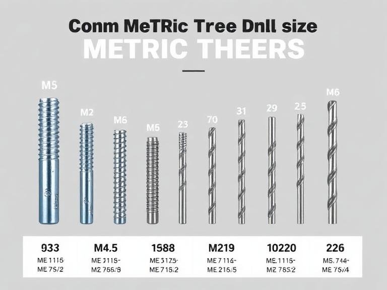
The transition toward global manufacturing standardization has cemented the ISO metric thread profile as the dominant fastening system worldwide. Whether you are operating a multi-axis CNC mill or hand-tapping a custom bracket on your workbench, understanding the mathematical relationship between the major diameter, the thread pitch, and the tapping drill size is non-negotiable. In this comprehensive, practitioner-level guide, we will break down the precise mechanics of thread tapping, detail the exact drill requirements for the 11 most common Metric Thread Sizes, and provide you with the commercial and practical judgment necessary to optimize your tooling arsenal.
Quick Answer: The Metric Drill Size Formula
The relationship between Metric Thread Sizes and their required drill sizes is defined by a simple, universally accepted formula: Drill Size = Nominal Tap Diameter – Thread Pitch. For example, to tap a standard M8 x 1.25 hole, you subtract the pitch (1.25) from the nominal diameter (8.0). This equals 6.75mm. In practical machining, rounding up slightly to a 6.8mm drill bit provides the perfect balance of 75% thread engagement and tap clearance, preventing tool breakage while ensuring maximum fastener holding power.
Table of Contents
- What Are Metric Thread Sizes?
- How Thread Tapping Works
- Quick Summary Table: 11 Common Metric Thread Sizes
- Detailed Breakdown of the 11 Sizes
- The Benefits of Metric Standardization
- Limitations to Consider
- Pros and Cons: Coarse vs. Fine Metric Threads
- Who Should Use It & Who Does Not Need It
- Comparison Table: Metric vs. Imperial (UN)
- Common Machining Mistakes
- Buying Considerations
- Expert Recommendation from MisolTap
- Frequently Asked Questions
What Are Metric Thread Sizes?
Metric Thread Sizes refer to the internationally recognized standard for screw threads, defined primarily by the International Organization for Standardization (ISO). These threads are identified by a capital “M” followed by the nominal major diameter in millimeters, and then the thread pitch (the distance between adjacent thread crests in millimeters). A thread designated as M10 x 1.5 indicates a 10mm outer diameter with a 1.5mm distance between each thread.
The geometry of Metric Thread Sizes is strictly defined by a 60-degree symmetrical V-shaped flank angle. This standardization ensures that a bolt manufactured in Germany will perfectly mate with a tapped hole machined in Japan. Unlike legacy imperial systems that rely on threads-per-inch (TPI), the metric system’s reliance on direct pitch measurement makes engineering calculations significantly more intuitive.
How Thread Tapping Works
Understanding how to use a thread tap requires recognizing that a tap does not remove all the material in a hole; it only cuts the female thread grooves into the pre-existing walls of a cylindrical bore. Therefore, the pre-drilled hole (the minor diameter) must be precisely sized. If the hole is too small, the tap will require excessive torque to force its way through the metal, resulting in catastrophic tool breakage. If the hole is too large, the tap will cut shallow grooves, leaving you with weak threads that will strip under load.
In most professional situations, machinists aim for roughly 75% thread engagement. This specific percentage offers optimal fastening strength while leaving enough clearance to evacuate metal chips during the cutting process. To achieve this, relying on an accurate tap and drill size chart is a fundamental requirement on any shop floor.
| Metric Thread Designation | Nominal Diameter (mm) | Thread Pitch (mm) | Recommended Drill Size (mm) |
|---|---|---|---|
| M3 x 0.5 | 3.0 | 0.5 | 2.5 |
| M4 x 0.7 | 4.0 | 0.7 | 3.3 |
| M5 x 0.8 | 5.0 | 0.8 | 4.2 |
| M6 x 1.0 | 6.0 | 1.0 | 5.0 |
| M8 x 1.25 | 8.0 | 1.25 | 6.8 |
| M10 x 1.5 | 10.0 | 1.5 | 8.5 |
| M12 x 1.75 | 12.0 | 1.75 | 10.2 |
| M14 x 2.0 | 14.0 | 2.0 | 12.0 |
| M16 x 2.0 | 16.0 | 2.0 | 14.0 |
| M20 x 2.5 | 20.0 | 2.5 | 17.5 |
| M24 x 3.0 | 24.0 | 3.0 | 21.0 |
Detailed Breakdown of the 11 Sizes
To fully grasp the utility of these Metric Thread Sizes, we must examine their real-world applications. Not all threads are created equal, and specifying the wrong size for your operational load will lead to mechanical failure.
- M3 to M5 (Micro & Precision): These smaller Metric Thread Sizes are the backbone of the electronics and 3D printing industries. M3 threads are universally used for PCB standoffs and computer chassis assembly. M5 threads bridge the gap into light mechanical assemblies, frequently found in bicycle components and optical mounts.
- M6 to M10 (General Purpose): This mid-range tier is ubiquitous across automotive interiors, robotics, and consumer appliances. M6 and M8 are arguably the most common Metric Thread Sizes you will encounter. M8 bolts secure engine brackets, while M10 threads are often utilized for medium-load suspension components and heavy-duty shelving mounts.
- M12 to M16 (Heavy Structural): When load-bearing integrity becomes critical, machinists turn to these sizes. M12 threads are standard for heavy automotive suspension parts and structural steel connections. M14 is famously the standard size for automotive wheel lug nuts, requiring massive shear strength. M16 threads are reserved for heavy industrial machinery base plates.
- M20 to M24 (Industrial & Heavy-Duty): For heavy-duty applications, these massive Metric Thread Sizes are utilized. You will find M20 and M24 threads securing bridge girders, heavy earth-moving equipment, and massive hydraulic cylinders. Tapping these sizes requires specialized heavy-duty machinery, as hand tapping a 24mm hole in steel is practically impossible.
The Benefits of Metric Standardization
The primary benefit of standardizing to Metric Thread Sizes is global supply chain compatibility. When engineering a product in the United States that will eventually be assembled in Europe or Asia, utilizing metric hardware guarantees that local technicians will have the correct tools and replacement fasteners readily available. Furthermore, the mathematical simplicity of the metric system eliminates the cumbersome fractional math associated with imperial measurements.
Additionally, modern tooling allows for incredible versatility. For specific rotational mechanics, engineers can easily source a left hand thread tap set in standard metric dimensions, ensuring that rotating shafts (like bicycle pedals or grinder arbors) do not self-loosen during operation.
Limitations to Consider
We exercise commercial and practical judgment when advising clients: transitioning entirely to Metric Thread Sizes presents specific logistical hurdles if you operate a legacy machine shop. The primary limitation is the initial capital expenditure required to replace imperial drill bit indexes and tap sets. Furthermore, attempting to force a metric bolt into an imperial threaded hole (or vice versa) because they “look similar” will instantly cross-thread and destroy the component.
| Thread Type | Pros | Cons |
|---|---|---|
| Standard (Coarse) Pitch | Faster to tap and assemble; highly resistant to cross-threading; excellent for general assembly and soft materials like aluminum. | Lesser tensile strength compared to fine threads; more susceptible to loosening from heavy vibration. |
| Fine Pitch | Superior tensile strength; excellent resistance to vibration-induced loosening; ideal for thin-walled materials. | Slower to assemble; highly susceptible to cross-threading and thread galling if not aligned perfectly. |
Who Should Use It & Who Does Not Need It
For commercial users and modern manufacturers: If you are designing consumer goods, robotics, automotive parts, or any product destined for international markets, you must exclusively utilize Metric Thread Sizes. The National Institute of Standards and Technology (NIST) heavily advocates for metrication in modern engineering to ensure global interoperability.
Who does not need it: If you operate a specialized restoration shop focusing on vintage American automobiles, classic aviation, or legacy industrial plumbing, converting to metric is unnecessary and detrimental. In these highly specific niches, Unified National (UN) and National Pipe Taper (NPT) threads remain the absolute standard.
| Feature | Metric Thread Sizes (ISO) | Imperial Threads (UN / SAE) |
|---|---|---|
| Identification | M + Diameter (mm) x Pitch (mm) | Fractional Diameter (inch) – TPI |
| Example | M8 x 1.25 | 5/16″ – 18 |
| Flank Angle | 60 Degrees | 60 Degrees |
| Drill Calculation | Simple subtraction (Diameter – Pitch) | Requires complex fractional charts (e.g., 1/2 thread tap size chart) |
| Global Usage | Dominant worldwide standard | Primarily localized to the USA and legacy aerospace |
Common Machining Mistakes
In our testing and daily interactions with commercial machine shops, we witness the same catastrophic errors repeatedly. Mastering how to tap threads in metal requires discipline. The most egregious mistake is “dry tapping”—running a tap into a raw hole without high-quality cutting fluid. Friction generates immense heat, causing the metal chips to weld themselves to the cutting flutes (galling), which eventually snaps the tap.
Another profound mistake is failing to chamfer the hole before tapping. A countersink chamfer provides a lead-in guide for the tap, ensuring it starts perfectly perpendicular to the workpiece. Finally, operators frequently misunderstand the application of thread repair tools. When salvaging damaged parts, utilizing dedicated rethreading taps and dies (thread chasers) is critical. Running a standard cutting tap through a damaged thread will remove more material and permanently weaken the joint.
Buying Considerations
When procuring taps for Metric Thread Sizes, commercial buyers must prioritize material science and flute geometry. The best material for thread taps depends entirely on the workpiece. High-Speed Steel (HSS) is the baseline standard, but if you are tapping abrasive materials like stainless steel or Inconel, upgrading to Cobalt-alloyed HSS (HSS-E) or powdered metal taps is mandatory.
Furthermore, you must evaluate the geometry based on the hole type. Knowing the plug tap vs thread tap distinction is vital. Plug taps are excellent for through-holes, but tapping a blind hole requires a bottoming tap to reach the base. Finally, resolving the debate of machine tap vs hand tap comes down to your equipment. Spiral point machine taps are designed to push chips forward ahead of the cut in CNC operations, whereas straight flute hand taps are designed for manual, reversible chip breaking.
Expert Recommendation from MisolTap
In most professional situations, the cost of a broken tap far exceeds the cost of a premium cutting tool. Attempting to save a few dollars on generic, unbranded taps will ultimately destroy your production efficiency. We recommend upgrading to highly calibrated, specialized tooling designed specifically for the rigorous demands of modern CNC environments.
MisolTap (MisolGroup) has established itself as a leading manufacturer of high-performance thread cutting tools. We integrate R&D, production, and global sales into a seamless operation.
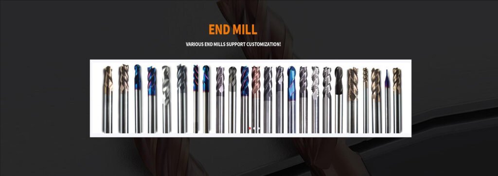
Our Capacity: With over 50 sets of 5-axis CNC grinding machines and in-house vacuum heat treatment, we ensure every tap meets the strictest tolerances. Whether you are producing intricate M3 aerospace housings or heavy-duty M24 structural components, our extensive catalog of coated, cobalt, and application-specific taps guarantees that your internal threads will gauge perfectly, every single time. Do not compromise on your tooling; invest in precision.
Frequently Asked Questions (FAQ)
How do I calculate the drill size for Metric Thread Sizes?
The industry standard formula for calculating the tapping drill size for metric threads is to subtract the thread pitch from the nominal major diameter. For example, for an M8 x 1.25 thread, the calculation is 8.0 – 1.25 = 6.75mm. A 6.8mm drill bit is typically used for practical clearance.
Can I use an imperial drill bit for a metric tap?
In most professional situations, we strongly advise against substituting imperial drill bits for metric tap drills. Metric Thread Sizes require precise minor diameters to achieve optimal thread engagement. Using an improperly sized imperial bit will result in stripped threads or broken taps during the machining process.
What is the difference between standard and fine Metric Thread Sizes?
Standard (coarse) Metric Thread Sizes have a larger pitch, making them faster to assemble and highly resistant to cross-threading, which is ideal for general manufacturing. Fine Metric Thread Sizes have a smaller pitch, providing greater tensile strength and superior resistance to vibration-induced loosening, making them critical for automotive and aerospace applications.
Authoritative Industry References
To ensure your machining processes adhere to the highest global standards, we advise referencing documentation from the following engineering authorities:
- International Organization for Standardization (ISO) – Official definitions and tolerance classes for ISO general purpose metric screw threads (ISO 261 and ISO 262).
- American Society of Mechanical Engineers (ASME) – Comprehensive engineering standards regarding thread geometry, gaging, and mechanical fastener performance.
- National Institute of Standards and Technology (NIST) – U.S. government agency providing rigorous guidelines on manufacturing metrology and global metrication standards.