
There is no sound on a manufacturing floor quite as devastating as the sharp, metallic snap of a machine tap breaking inside a nearly finished, expensive aerospace billet. Tapping is almost always one of the final operations performed on a CNC machine. If you fail to determine tapping speed and feed correctly, you do not just lose a twenty-dollar cutting tool; you risk scrapping hours of prior milling, turning, and boring operations. Relying on default CAM software parameters or outdated wall charts is a commercial liability.
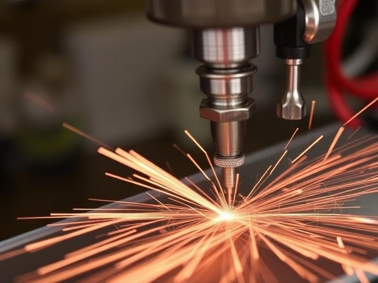
From our experience engineering precision cutting tools at MisolTap, treating threading as an afterthought is the primary cause of poor thread quality, torn flanks, and catastrophic tool failure. Precision internal threading is a brutally unforgiving mechanical operation. Unlike milling, where you can easily alter your chip load by tweaking the feed rate, a tap’s feed is mathematically locked to its rotation. To master this process, you must apply commercial and practical judgment to calculate the exact operational window for your specific application. In this guide, we break down the definitive variables that dictate how fast and how hard you can push your threading tools.
Quick Answer: How to Determine Tapping Speed and Feed
To accurately determine tapping speed and feed, you must calculate the exact mathematical relationship between the spindle RPM and the thread pitch, while adjusting for six critical operational variables. The formula for feed rate is Feed (IPM) = RPM x Thread Pitch (or 1/TPI). The six factors that dictate the maximum safe RPM are: 1. Workpiece material machinability, 2. Tap substrate and coating, 3. Thread pitch and profile geometry, 4. Hole type (blind vs. through), 5. Coolant concentration and lubricity, and 6. CNC machine spindle synchronization capabilities. Failing to balance these factors leads directly to tool breakage or oversized, out-of-tolerance threads.
Table of Contents
- What It Is: The Mechanics of Tapping Speeds and Feeds
- How It Works: The Unbreakable Mathematical Link
- The 6 Factors That Determine Tapping Speed and Feed
- Benefits of Optimizing Your Parameters
- Limitations and Edge Cases
- Who Should Use Calculated Feeds (And Who Does Not Need To)
- Common Mistakes in Threading Operations
- Buying Considerations for High-Performance Taps
- Summary, Comparison, and Pros vs Cons Tables
- Expert Recommendation from MisolTap
- Frequently Asked Questions (FAQ)
What It Is: The Mechanics of Tapping Speeds and Feeds
In the context of machining, “speed” refers to the Surface Feet per Minute (SFM) or spindle Revolutions Per Minute (RPM)—how fast the cutting edge of the tap moves against the workpiece. “Feed” refers to the linear velocity of the tool plunging into the Z-axis, usually measured in Inches Per Minute (IPM) or millimeters per minute (mm/min).
When you seek to determine tapping speed and feed, you are looking for the optimal thermal and mechanical window. If you run the speed too slow, the material may adhere to the cutting edge, creating a built-up edge (BUE) that tears the threads. If you run it too fast, the extreme friction will instantly burn off the tool’s protective coating, softening the high-speed steel or carbide substrate until the cutting teeth shear off entirely.
How It Works: The Unbreakable Mathematical Link
Understanding the difference between a machine tap vs hand tap is crucial here. When hand tapping, human feel dictates the pace. In CNC machining, the feed rate is mathematically tethered to the RPM by the pitch of the thread. You cannot arbitrarily slow down the feed rate to thin out the chip load as you would with an endmill. If you program an RPM of 400 for a 1/4-20 tap (20 threads per inch), the tap must advance exactly one inch for every 20 revolutions. Therefore, the feed rate must be exactly 20 IPM. If the spindle rotation and the Z-axis feed do not perfectly match this ratio, the tap will shave the flanks of the thread, destroying the part tolerance.
The 6 Factors That Determine Tapping Speed and Feed
In most professional situations, establishing your baseline parameters requires evaluating the following six factors sequentially.
1. Workpiece Material Machinability
The metallurgical properties of your workpiece are the foundation of your speed calculations. Free-machining aluminum allows for highly aggressive SFM (often exceeding 100 SFM), while work-hardening materials like 304 Stainless Steel or Inconel demand significantly lower speeds (15 to 30 SFM) to prevent instantaneous tool failure. The hardness and tensile strength dictate how much shear force is required, which directly translates to heat generation in the cutting zone.
2. Tap Substrate and Coating
Not all taps are created equal. A basic uncoated High-Speed Steel (HSS) tap will burn up at speeds where a premium Cobalt-alloyed (HSSE) or solid carbide tap coated with Titanium Carbonitride (TiCN) will thrive. Coatings provide thermal barriers and increase surface lubricity. When procuring tooling from a premium din371 thread tap supplier, you are paying for advanced geometries and coatings that allow you to push your RPMs 30% to 50% higher than standard uncoated tools.
3. Thread Pitch and Profile Geometry
The pitch of the thread dictates the volume of material removed per revolution. Coarse threads remove massive amounts of material quickly, generating extreme torque loads. Fine threads remove less material per revolution, allowing for slightly higher spindle speeds. Consulting an accurate tap and drill size chart is mandatory to ensure you are leaving the correct percentage of thread (usually 60% to 75%) to prevent overloading the tool.
4. Hole Type: Blind vs. Through-Hole
Chip evacuation is the enemy of all threading operations. In a through-hole, a spiral point tap shoots the chips forward, clearing the path safely, which allows for faster speeds. In a blind hole, the chips must be pulled up and out using a spiral flute tap. Understanding the plug tap vs thread tap dynamics is vital; pushing a tap too fast into a deep blind hole guarantees that chips will pack at the bottom, causing a severe torque spike and immediate breakage.
5. Coolant Concentration and Lubricity
Tapping generates more friction than almost any other machining operation. Standard flood coolant running at a lean 5% concentration is often inadequate for heavy-duty threading. To determine tapping speed and feed effectively, you must account for lubricity. Upgrading to a 10% to 12% coolant concentration, or utilizing specialized tapping fluids/pastes, drastically reduces friction, allowing you to maintain higher SFM without galling the threads.
6. CNC Machine Spindle Capabilities
Your theoretical calculations mean nothing if your CNC machine lacks the physical capability to execute them. Modern machines feature “Rigid Tapping” cycles (G84 on Fanuc controls), which utilize high-resolution encoders to perfectly synchronize the spindle deceleration, reversal, and Z-axis retraction. If you are operating an older machine with servo lag, you must use a tension-compression (floating) tap holder and program a more conservative speed to allow the internal spring to compensate for the mechanical slop.
Benefits of Optimizing Your Parameters
For commercial users, the benefits of dialing in these six factors are purely financial. Optimizing speeds and feeds drastically extends tool life, meaning you buy fewer expensive taps per production run. Furthermore, correct synchronization ensures gauge-perfect threads that will never fail a Go/No-Go inspection, completely eliminating the scrap costs associated with oversized or torn threads. Cycle time reductions across thousands of holes also free up valuable spindle hours for other jobs.
Limitations and Edge Cases
The primary limitation when calculating these parameters is material inconsistency. If you are tapping into cheap, porous castings with hard inclusions, even the most perfectly calculated feed rate will not save the tool from a sudden spike in hardness. Additionally, very deep holes (greater than 3xD) completely invalidate standard speed charts. In these edge cases, you must manually reduce your SFM by 20% to 40% and utilize peck-tapping cycles to break chips safely.
Who Should Use Calculated Feeds (And Who Does Not Need To)
We recommend strict adherence to calculated speeds and feeds for CNC programmers, manufacturing engineers, and setup machinists operating industrial milling and turning centers. If you are running production batches, guessing is not an option.
Who does not need this level of mathematical rigor? Hobbyists, maintenance technicians, and fabricators who are manually tapping holes using a T-handle wrench. If you simply need to know how to use a thread tap safely by hand or want basic instructions on how to tap threads in metal for a one-off repair, focusing on keeping the tool straight and using generous amounts of cutting oil is far more important than calculating SFM.
Common Mistakes in Threading Operations
In our testing and field observations, the most destructive mistake programmers make is neglecting the core drill size. Drilling a hole too small increases the thread percentage to 85% or 90%. This requires exponentially more torque to cut, guaranteeing tool breakage regardless of how perfect your speed and feed calculations are. Whether you are consulting a standard metric chart or a specific 1/2 thread tap size chart, always aim for a 65% to 75% thread engagement for commercial applications.
Another common failure is using the wrong tap geometry for the job. Attempting to use a left hand thread tap set designed for hand-repair work inside a high-speed CNC spindle will result in disaster. Always match the tool geometry to the specific machine dynamic.
Buying Considerations for High-Performance Taps
When procuring tooling, do not buy based on initial cost. A ten-dollar uncoated HSS tap that breaks after fifty holes is vastly more expensive than a thirty-dollar TiCN-coated HSSE tap that lasts for a thousand holes. For heavy-duty applications, we advise partnering directly with an ios 529 thread tap supplier who can provide explicit speed and feed recommendations tailored to their specific tool geometries and coatings.
Summary, Comparison, and Pros vs Cons Tables
| Factor | Impact on Operation | Required Adjustment |
|---|---|---|
| Material Hardness | Determines shear force and heat generation. | Harder materials require much lower RPM. |
| Tap Coating | Provides lubricity and thermal resistance. | Premium coatings allow for 30%+ higher speeds. |
| Thread Pitch | Locks the feed rate to the RPM. | Coarse pitches require lower RPM due to heavy chip loads. |
| Hole Geometry | Dictates chip evacuation strategy. | Blind holes require slower speeds and spiral flutes. |
| Coolant Quality | Reduces cutting friction and galling. | Rich concentration (10%+) needed for optimal speeds. |
| Machine Sync | Dictates rigid vs floating execution. | Older machines need floating holders and conservative feeds. |
| Feature | Rigid Tapping (Modern CNC) | Tension-Compression Holder |
|---|---|---|
| Spindle/Axis Sync | Perfect electronic synchronization. | Relies on physical spring compression. |
| Speed Capabilities | Allows for maximum calculated RPM and fast retracts. | Requires slower RPM to prevent spring bounce. |
| Thread Depth Accuracy | Exact depth control for blind holes. | Variable depth control (+/- slight spring travel). |
| Best Use Case | High-volume, high-precision production. | Older machines lacking encoder feedback. |
| Approach | Pros | Cons |
|---|---|---|
| Aggressive Speeds (High RPM) | Faster cycle times; prevents built-up edge in soft materials like aluminum. | High risk of burning tool coatings; catastrophic failure if coolant supply drops. |
| Conservative Speeds (Low RPM) | Extends tool life in tough alloys; safer for deep blind holes and manual operations. | Slower production; risk of material tearing or galling in softer, gummy metals. |
Expert Recommendation from MisolTap
We recommend abandoning the practice of copying and pasting speed and feed data from generic internet forums. Your production environment is unique. Start with the manufacturer’s recommended Surface Feet per Minute (SFM) for your specific material, calculate your RPM, and set your feed rate using the unbreakable Feed = RPM x Pitch formula. If you are experiencing tool wear, do not immediately slow down the RPM—first check your coolant concentration and ensure your pre-drill size is providing a safe 70% thread engagement.
Partner with MisolTap for Precision Threading
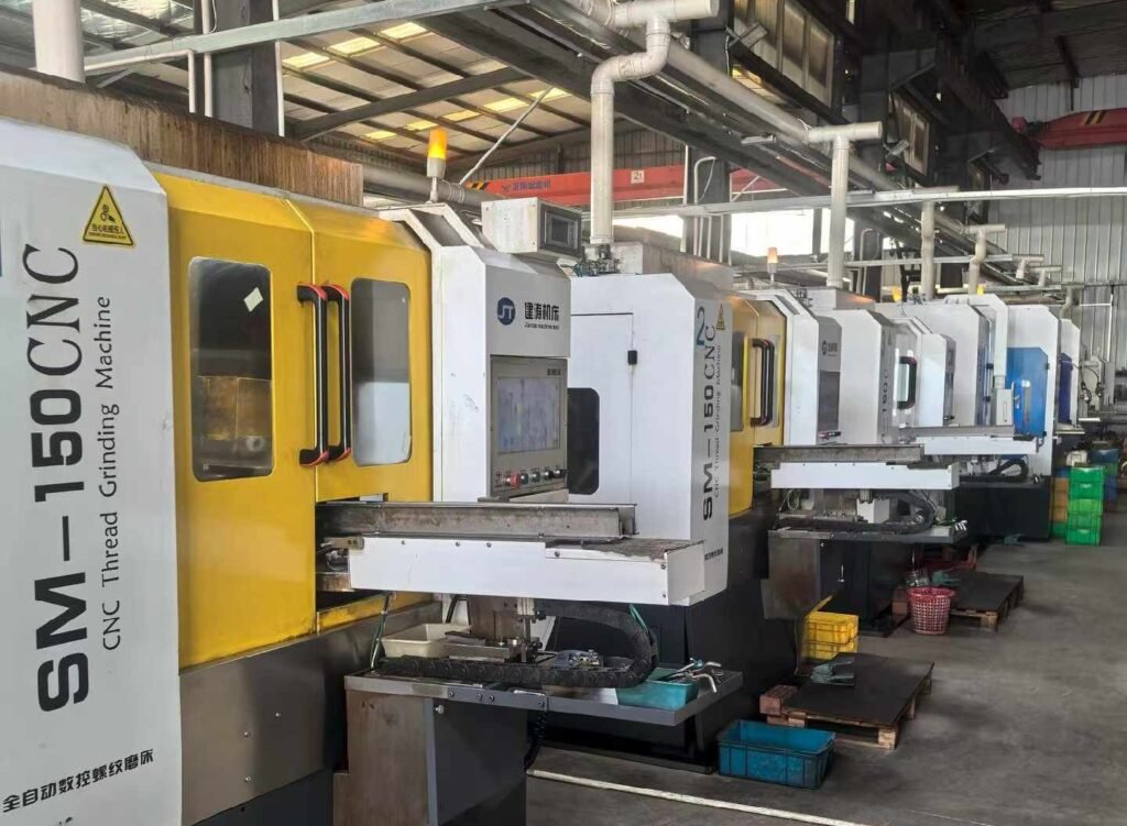
Since our founding in 2005, MisolTap has established itself as a leading Chinese manufacturer of high-performance thread cutting tools.
We integrate R&D, production, and global sales into a seamless operation, providing our clients with robust and precise threading solutions tailored to modern manufacturing needs. Whether you are tapping aerospace titanium or high-volume automotive aluminum, our engineered coatings and geometries ensure you can push your CNC parameters to the maximum safe limit without sacrificing thread quality.
Frequently Asked Questions (FAQ)
How do you calculate the feed rate for tapping?
The feed rate for tapping is mathematically locked to the spindle speed and the thread pitch. For Imperial threads, the formula is: Feed Rate (Inches Per Minute) = RPM divided by Threads Per Inch (TPI). For Metric threads, the formula is: Feed Rate (Millimeters Per Minute) = RPM multiplied by the Pitch (in mm).
What happens if my tapping speed is too slow?
Running a tap too slowly, especially in softer materials like aluminum or low-carbon steel, often leads to a Built-Up Edge (BUE). The material adheres to the cutting face of the tap, which alters the geometry of the tool and results in torn, rough, or oversized threads.
Why does a blind hole require different tapping parameters than a through-hole?
In a through-hole, the chips are pushed forward and fall out the bottom. In a blind hole, the chips have nowhere to go and must be pulled upward along the flutes. If the speed is too high or the wrong tap geometry (like a spiral point instead of a spiral flute) is used, chips pack tightly at the bottom of the hole, causing a massive torque spike that will instantly snap the tap.
Can I use standard CNC coolant for heavy tapping?
Standard flood coolant is primarily designed for cooling, not extreme lubrication. Tapping generates immense friction. If you are tapping tough materials like stainless steel, a standard 5% coolant concentration is often too lean. You must increase the concentration to 10%-12% or utilize dedicated tapping fluids to prevent tool failure.
Authoritative Industry References
To ensure robust engineering principles and accurate machining calculations, the methodologies in this guide are cross-referenced with the following authoritative standards:
- Machinery’s Handbook (Industrial Press) – The definitive standard for mechanical engineering, thread geometry, and machining calculations.
- International Organization for Standardization (ISO) – Technical Committee 29/SC 2 – Global standards for cutting tools, including tap dimensions and tolerances.
- Modern Machine Shop – Leading industrial publication detailing advanced CNC rigid tapping cycles and tooling technologies.