
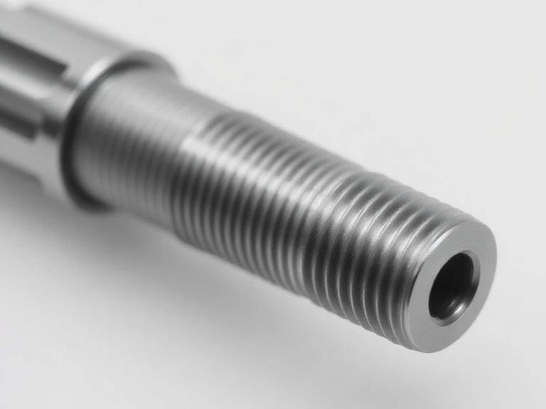
Machining internal threads is a high-stakes operation. Unlike external threads, which are completely exposed and relatively easy to inspect with a set of micrometers, a tapped hole hides its critical dimensions in the dark. From our experience manufacturing industrial cutting tools since 2005, the most common point of failure in a production run is not the tapping process itself, but the failure to accurately measure internal threads post-machining. A hole that looks perfectly threaded to the naked eye can be oversized by just two-thousandths of an inch, resulting in catastrophic fastener pull-out under heavy loads.
At MisolTap, we do not tolerate guesswork on the shop floor. Whether you are cutting NPT threads for high-pressure hydraulics or metric threads for aerospace components, verification is mandatory. In this commercial guide, we take a firm position on inspection protocols. We will dissect the exact physical tools and processes you must use to measure internal threads, explain the limitations of visual inspection, and help you determine which method is economically and mechanically viable for your specific production volume.
Quick Answer: How Do You Accurately Measure Internal Threads?
To accurately measure internal threads, you must move beyond visual estimation and utilize calibrated metrology tools. The absolute best and most efficient method for production environments is using a Thread Plug Gage (Go/No-Go Gauge). This tool provides an immediate pass/fail mechanical verification of the pitch diameter and functional thread form. For precise numerical data or reverse-engineering unknown threads, utilizing Thread Pitch Gauges combined with an Inside Micrometer or casting the hole with Repro-Rubber for optical comparison are the most reliable methods. We recommend avoiding cheap digital calipers for internal thread measurements, as their jaws cannot physically reach the root of the internal thread profile.
Table of Contents
- What It Is: The Anatomy of an Internal Thread
- How Measurement Actually Works
- Method 1: Thread Plug Gages (Go/No-Go)
- Method 2: Thread Pitch Gauges
- Method 3: Inside Micrometers and Calipers
- Method 4: Casting with Repro-Rubber
- Method 5: Coordinate Measuring Machines (CMM)
- The Strategic Benefits of Measurement
- Limitations in the Field
- Who Should Use It & Who Does Not Need It
- Common Machining Mistakes
- Comparison Table: Measurement Methods
- Pros and Cons Table
- Expert Recommendation
- The Bottom Line
- Frequently Asked Questions
What It Is: The Anatomy of an Internal Thread
Before you can accurately measure an internal thread, you must understand what you are actually trying to quantify. An internal thread (a tapped hole) consists of three critical diameters. The Minor Diameter is the smallest diameter of the thread, essentially the size of the hole you drill before tapping. The Major Diameter is the largest diameter, located at the root (the deepest cut) of the thread. However, the most critical dimension is the Pitch Diameter. This is the theoretical cylinder where the width of the thread ridge equals the width of the thread groove. In most professional situations, when an engineer says a thread is “out of tolerance,” they are referring to a failed pitch diameter.
How Measurement Actually Works
Measuring internal threads works by validating these diameters and the thread pitch (the distance between crests). Because you cannot easily get measurement anvils inside a small tapped hole, we rely heavily on transfer methods (like casting) or functional limit gauges. If you are learning how to utilize various types of thread taps, your inspection method must align with your tap style. A roll form tap displaces metal, creating a slightly different internal profile than a cut tap, requiring strict adherence to pitch diameter verification.
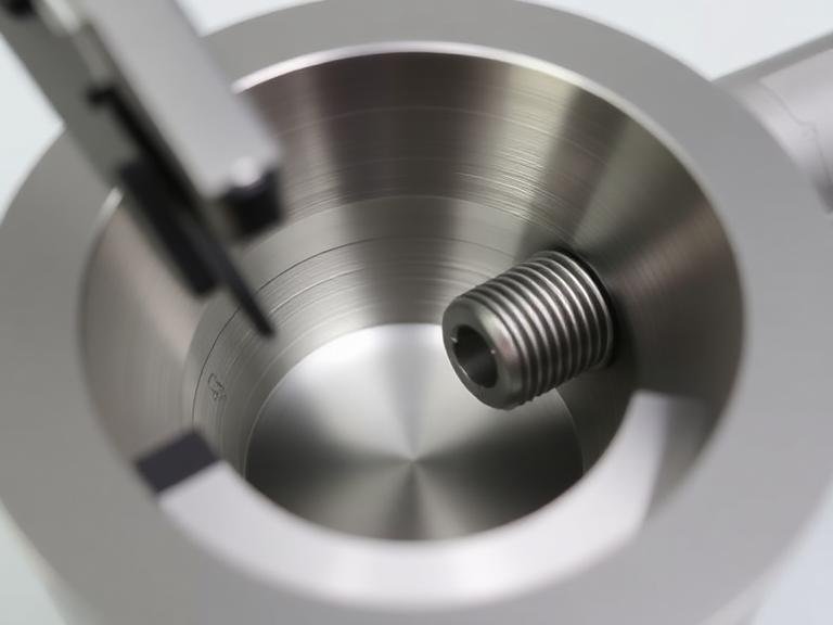
Method 1: Thread Plug Gages (Go/No-Go)
For commercial users and high-volume production: This is the undisputed champion of the shop floor. A thread plug gauge consists of two ends. The “Go” end is machined to the minimum material limit. If the hole is tapped correctly, the “Go” gauge should screw all the way in with zero resistance. The “No-Go” end is machined to the maximum material limit; it should only engage by one or two threads before binding. If the No-Go gauge screws all the way in, your hole is oversized and the part is scrap. It is binary, fast, and removes human error.
Method 2: Thread Pitch Gauges
If you are reverse-engineering a broken part and need to determine the TPI (Threads Per Inch) or metric pitch, a thread pitch gauge is required. This looks like a pocket knife with dozens of serrated steel blades. You press the blades against the internal threads until the teeth of the blade interlock perfectly with the threads in the hole without letting light pass through. While this identifies the pitch, it does not measure the diameter.
Method 3: Inside Micrometers and Calipers
Calipers are highly problematic for measuring internal threads because the flat jaws bridge the thread crests and cannot reach the pitch diameter. However, specialized inside micrometers with interchangeable thread-measuring anvils (ball and cone points) can accurately measure the pitch diameter. In our testing, this method is slow and requires significant operator skill, making it unsuitable for rapid production but excellent for precise R&D measurements.
Method 4: Casting with Repro-Rubber
When dealing with deep blind holes or complex tapered threads (like identifying a pipe thread tap size chart specification), getting physical tools inside the hole is impossible. The solution is Repro-Rubber. You inject this fast-curing silicone compound into the hole, wait three minutes, and unscrew the flexible plug. You have just turned an internal thread into an external thread, which you can now easily measure with standard optical comparators or external micrometers.
Method 5: Coordinate Measuring Machines (CMM)
For heavy-duty applications and aerospace: When tolerances are measured in tenths of a thousandth, functional Go/No-Go gauges are not enough. A CMM uses a ruby-tipped stylus to physically map the internal geometry of the thread, generating a 3D digital model. This provides exact numerical data on the pitch diameter, flank angle, and lead error. It is incredibly expensive and slow, but absolute perfection is guaranteed.
The Strategic Benefits of Measurement
Why spend money on expensive gauges? The primary benefit is liability prevention. A stripped thread in an automotive brake caliper or a high-pressure manifold results in catastrophic failure. By verifying every threaded hole, you ensure fastener retention strength. Furthermore, utilizing proper measurement tools allows you to identify tap wear early. If your “Go” gauge starts feeling tight, you know the tap is dulling before it breaks inside a costly workpiece. This is a core reason why selecting the best material for thread taps is critical for longevity.
Limitations in the Field
The main limitation of functional limit gauges (Go/No-Go) is that they do not tell you why a thread failed. If the No-Go gauge enters the hole, you know the hole is bad, but you don’t know if the issue is a worn tap, chip packing, or incorrect drilling speed for metal that caused an oversized pre-drill hole. You still need diagnostic skills to correct the machining process.
Who Should Use It & Who Does Not Need It
For commercial users and CNC operators: You must own a complete set of certified Go/No-Go thread plug gages for every thread size you run. It is non-negotiable. If you are cutting specialized threads, such as reverse thread taps (left-hand threads), you must purchase left-hand specific gauges.
For beginners and DIY hobbyists: If you are simply tapping a hole in a bracket to hold a license plate, buying a $100 calibrated thread gage is overkill. You can “gauge” the hole by simply driving the actual mating bolt into the hole. If it threads smoothly without excessive wobble, it is acceptable for non-critical loads.
Common Machining Mistakes
The most pervasive mistake we see is using a bolt as a permanent gauge in a commercial setting. Fasteners are manufactured with massive tolerances. A bolt might thread perfectly into an oversized hole, masking a dangerous lack of thread engagement. You cannot use a Class 2A bolt to verify a Class 2B internal thread accurately.
Another severe error is forcing a Go/No-Go gauge. If the Go gauge stops halfway down the hole, do not grab a wrench and force it. You will destroy the calibrated threads on the gauge. If it stops, the hole is undersized or packed with chips. Stop and investigate.
Comparison Table: Measurement Methods
| Measurement Method | Speed of Use | Accuracy Level | Best Application |
|---|---|---|---|
| Go/No-Go Plug Gage | Very Fast | Functional Pass/Fail | CNC Production Lines |
| Thread Pitch Gauge | Fast | Pitch Only (Not Diameter) | Reverse Engineering Parts |
| Repro-Rubber Casting | Slow | High (when measured optically) | Deep Blind Holes / Tapered Pipe Threads |
| CMM (Stylus Profiling) | Very Slow | Absolute Perfection | Aerospace / Medical Devices |
Pros and Cons Table: Limit Gaging vs Numerical Measurement
| Pros of Functional Gaging (Go/No-Go) | Cons of Functional Gaging |
|---|---|
| Requires zero mathematical calculation by the operator. | Provides no specific dimensional data (only pass/fail). |
| Extremely fast to deploy on a high-volume production line. | Gauges wear out over time and require recalibration/replacement. |
| Simulates the actual mating of the fastener. | Cannot diagnose specific thread form errors (e.g., flank angle). |
| Relatively inexpensive compared to electronic measuring systems. | You must buy a separate gauge for every single thread size and class. |
Commercial Buying Considerations
When equipping your shop, you must understand thread classes. A 1/4-20 Class 2B gauge is not the same as a 1/4-20 Class 3B gauge. Class 3B represents a much tighter tolerance for aerospace and high-vibration environments. If you use a 2B gauge on a 3B drawing requirement, you will ship non-conforming parts. Additionally, if you are machining hard materials, your taps will wear faster. Utilizing a heavy duty tap and drill combination requires aggressive, frequent gauging to ensure the tap hasn’t lost its pitch diameter through abrasive wear.
Expert Recommendation
The MisolTap Engineering Verdict
In most professional situations, trying to save money on metrology guarantees you will lose money on scrapped parts. We recommend a hybrid approach. Every CNC operator must have a calibrated Go/No-Go thread plug gauge at their station for immediate, part-by-part verification. However, your Quality Control department must have access to casting rubber or a CMM to diagnose why a tap is failing. Furthermore, do not buy cheap gauges. Since our founding in 2005, MisolTap has established itself as a leading Chinese manufacturer of high-performance thread cutting tools. We integrate R&D, production, and global sales into a seamless operation, providing our clients with robust and precise threading solutions. We know that precision cutting requires precision measurement. If you are comparing thread tap manufacturers, ensure they also advocate for strict, class-specific gauging protocols.
The Bottom Line
To accurately measure internal threads, you must abandon visual guesswork. The pitch diameter is the single most critical dimension for fastener retention, and it can only be reliably verified using functional limit gauges (Go/No-Go plugs) or advanced internal profiling. Whether you are chasing the tolerances on a complex 3/8 pipe thread tap size or simply restoring a stripped block with rethreading taps and dies, establishing a rigid inspection protocol protects your liability, prevents part failure, and ultimately guarantees the mechanical integrity of your manufacturing operation.
Frequently Asked Questions
Why can’t I just use a digital caliper to measure an internal thread?
A standard digital caliper has flat, wide jaws. When you insert them into a tapped hole, the jaws rest on the crests (the peaks) of the internal thread. They cannot physically reach down into the root or the pitch line of the thread. Therefore, a caliper can only give you a rough estimate of the minor diameter, which tells you nothing about the functional thread engagement.
What does it mean if the “Go” gauge will not screw into the hole?
If the “Go” plug gauge binds or refuses to enter the tapped hole, it means the hole is undersized (there is too much material left in the hole). This is typically caused by a severely worn tap that has lost its cutting edges, or the hole is packed with un-evacuated metal chips that are blocking the thread path.
Is there a difference between measuring cut threads and roll-formed threads?
The inspection method (using a Go/No-Go plug gauge) is exactly the same for both. However, the pre-drilled hole size is radically different. Roll forming displaces metal rather than cutting it, so the minor diameter before tapping is much larger. If you measure the minor diameter of a rolled thread, it may appear slightly different than a cut thread, but the pitch diameter—which the plug gauge measures—must be identical to pass inspection.
Authoritative Industry References
- American Society of Mechanical Engineers (ASME) – Standards for Unified Inch Screw Threads (ASME B1.1) and gauging protocols.
- International Organization for Standardization (ISO) – ISO 1502:1996 standards for general-purpose metric screw threads and limit gauges.
- National Institute of Standards and Technology (NIST) – Metrology standards and calibration traceability for industrial measurement tools.