
In metalworking and CNC precision manufacturing, terminological confusion regularly leads to expensive tooling mistakes. Machinists and procurement managers often hear the terms “threading” and “tapping” used interchangeably on the shop floor. While both processes share the ultimate goal of creating a helical ridge to receive a threaded fastener, treating them as identical operations is a fundamental error. Understanding the exact differences between threading and tapping is essential for optimizing machine cycle times, selecting proper cutting tools, and eliminating costly workpiece scrap.
From our experience engineering cutting tools at MisolTap, shop owners frequently encounter tool failure, poor pitch diameter control, and shattered workpieces simply because they selected the wrong process for their specific hole geometry or material hardness. Threading represents a broad umbrella of manufacturing techniques, whereas tapping is a hyper-specific, high-efficiency method dedicated to internal thread cutting. In this comprehensive guide, we will break down the six primary differences between threading and tapping, analyze the mechanical trade-offs of each approach, and provide practical decision-making criteria for your machining operations.
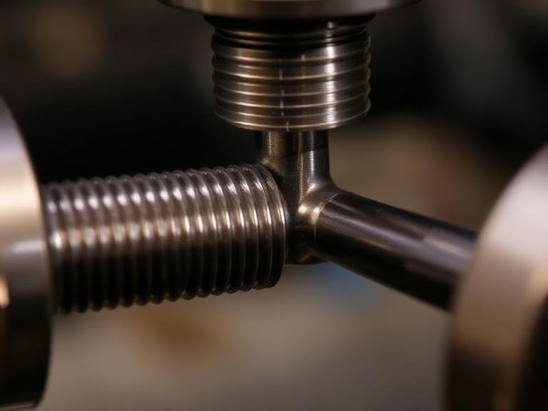
Quick Answer: What Are the Key Differences Between Threading and Tapping?
The primary differences between threading and tapping center on process scope, tool geometry, and application site:
- Scope: Threading is the overall umbrella term for generating internal or external helical threads via lathe single-point tools, dies, rolling, or thread mills. Tapping is specifically the process of cutting or forming female internal threads using a dedicated tap body inside a pre-drilled hole.
- Feature Location: Threading applies to both internal bores and external shafts/rods. Tapping applies exclusively to internal holes.
- Tooling Mechanism: General threading uses single-point inserts, thread mills, or dies requiring multiple passes or interpolated paths. Tapping utilizes a multi-fluted tool that cuts the full thread profile in a single continuous axial pass.
- Chip Evacuation: Threading on external surfaces allows open chip dispersal, while tapping operates in confined blind or through holes where chip clearance in the flutes is critical to prevent tool breakage.
Table of Contents
- What It Is: Defining Threading vs Tapping
- How It Works: Kinematics and Mechanics
- The 6 Core Differences Between Threading and Tapping
- Commercial and Operational Benefits of Each Method
- Limitations and Mechanical Constraints
- Who Should Use Tapping vs Other Threading Methods
- Who Does Not Need Tapping
- Common Machining Mistakes to Avoid
- Tool Sourcing and Buying Considerations
- Expert Recommendation from MisolTap
- Technical and Data Comparison Tables
- Frequently Asked Questions (FAQ)
What It Is: Defining Threading vs Tapping
To grasp the foundational differences between threading and tapping, one must establish precise engineering definitions. Threading is the overarching manufacturing classification that encompasses any process used to produce a helical screw thread on a workpiece. This includes single-point lathe turning, thread milling, thread grinding, thread rolling, and die cutting. Threading can produce both external male threads (such as on bolts, studs, or lead screws) and internal female threads (such as in large-bore pipes or custom housings).
Tapping, on the other hand, is a specific internal threading technique. It relies on a hardened steel or carbide tool called a tap, which features full-form helical cutting teeth separated by flutes. As the tap rotates and advances into a pre-drilled pilot hole, its cutting teeth progressively carve out the internal thread form. If you are learning how to tap threads in metal, you are performing a localized, high-speed subset of internal threading.
How It Works: Kinematics and Mechanics
The kinematic differences between general threading processes and tapping dictate how cutting forces are distributed across the tool body.
In single-point lathe threading, a single carbide insert matches the pitch profile of the thread. The machine’s lead screw or CNC Z-axis synchronizes with the spindle rotation, driving the tool along the length of the workpiece in small, incremental depth passes (often requiring 6 to 15 passes to achieve final thread depth). Thread milling uses a rotating multi-tooth cutter that helical-interpolates around the perimeter of an internal or external feature.
In contrast, tapping works in a single, continuous axial pass. The tap contains a chamfer lead (taper, plug, or bottoming style) that distributes the total depth of cut across multiple successive teeth along the tool’s length. As the tap turns, each tooth removes a small chip until the full thread form is completed. To ensure proper execution, operators must consult a verified tap and drill size chart to guarantee that the pilot hole diameter leaves precisely the required percentage of thread (typically 65% to 75%).
The 6 Core Differences Between Threading and Tapping
In most professional situations, engineers differentiate these techniques across six distinct operational parameters:
1. Scope and Process Hierarchy
Threading is the master category; tapping is a specialized sub-category. Every tapping operation is a form of threading, but not all threading operations are tapping. Threading includes cold-forming (thread rolling), single-point turning, milling, and manual die cutting across male and female geometries. Tapping is strictly confined to female internal geometries generated by an axial tap tool body.
2. Internal vs. External Application Site
One of the most obvious differences between threading and tapping is physical geometry. General threading can create male threads on external shafts or female threads in massive cavities. Tapping cannot cut external threads on a stud or bolt. It is exclusively engineered for internal blind or through holes where a pre-drilled bore exists.
3. Tooling Architecture and Cutter Geometry
General threading tools frequently utilize indexable carbide inserts, thread milling bodies, or adjustable external dies. These tools allow operators to adjust thread pitch or depth by changing machine programming or insert shims. A thread tap, however, is a solid tool (HSS, HSS-Co, or Solid Carbide) ground to a fixed, unchangeable pitch and diameter profile. When utilizing specialized tooling like an ios 529 thread tap supplier product line, the thread form is permanently locked into the tool geometry.
4. Pass Count and Cycle Speed
Single-point lathe threading is inherently multi-pass. The tool must traverse the length of the thread, retract, rapidly return, step deeper in the X-axis, and repeat until the pitch diameter reaches tolerance. Tapping is a rapid single-pass operation. The tool enters, reaches depth, reverses spindle direction (or uses a reversing tapping head), and backs out. Tapping delivers vastly superior cycle times for standard hole sizes.
5. Chip Evacuation and Space Constraints
When performing external threading, chips fall away freely under gravity or coolant flush. Internal single-point turning offers open clearance for long continuous chips. Tapping takes place inside a cramped cylinder. The flutes on a tap (whether straight, spiral point, or spiral flute) must actively pull chips up and out of a blind hole or push them ahead through a through-hole. Chip packing inside tap flutes is the leading cause of tool breakage in metalworking.
6. Risk Profile and Tool Breakage Scrap Costs
If a single-point lathe insert chips during an external threading pass, the operator swaps the insert edge, cleans the thread, and continues the cut. If a thread tap snaps inside a deep blind hole in a high-value aerospace casting, the entire part is at risk of being scrapped or requiring hours of tedious Electrical Discharge Machining (EDM) extraction. The risk profile of tapping is inherently higher due to torsional stress buried inside the metal.
Commercial and Operational Benefits of Each Method
Evaluating whether to utilize direct tapping or alternative threading methods requires examining the commercial priorities of your production line:
- Benefits of Tapping:
- Unrivaled Production Speed: Completes internal threads in seconds via rigid tapping CNC cycles.
- Low Initial Capital Expenditure: Taps are significantly cheaper than specialized thread milling bodies or high-precision lathe threading bars.
- Operational Simplicity: Requires no complex helical interpolation macro programming; relies on basic feed-per-revolution synchronization. Exploring options from a certified din371 thread tap supplier allows shops to easily standardize tooling across machine units.
- Benefits of Alternative Threading (Lathe Single-Point & Thread Milling):
- Total Geometry Flexibility: A single 60-degree thread mill can cut internal threads of varying diameters as long as the pitch matches.
- Superior Thread Surface Finish: Allows light polishing passes to achieve high surface finish requirements on tough nickel alloys.
- Zero Extraction Risk: If a thread mill breaks, it does not lock itself solid inside the hole; the broken core simply falls out, preserving the workpiece.
Limitations and Mechanical Constraints
We must apply realistic engineering judgment: neither process is flawless. The primary limitation of tapping is its inflexibility. You cannot adjust the pitch diameter or class of fit beyond the ground limits ($H1-H6$ or $D1-D6$) of the specific tap. Furthermore, tapping very large diameters (above 2 inches or 50mm) requires massive machine torque that exceeds standard CNC spindle capacities.
The main limitation of single-point lathe threading or thread milling is machine cycle time. Single-point threading requires multiple passes, making it economically unviable for high-volume small-diameter hole tapping. Thread milling requires sophisticated multi-axis CNC machines and takes significantly longer per hole than a rapid rigid-tapping cycle.
Who Should Use Tapping vs Other Threading Methods
For commercial users and high-volume machine shops: We strongly recommend tapping for all standard-size internal holes (M2 to M30 or #2 to 1-1/8 inch) in structural steels, aluminum, brass, and ductile cast irons. When producing hundreds of threaded holes per shift, the time savings of single-pass tapping directly dictates profit margins. To optimize tool life, production managers should carefully analyze the differences between a machine tap vs hand tap prior to setting up automated operations.
When to choose alternative threading (Single-Point or Thread Milling): For heavy-duty applications involving hardened steel alloys (>45 HRC), thin-walled tubular parts prone to cracking under tap expansion pressure, or massive diameter internal bores, thread milling or lathe single-point turning is vastly superior to tapping.
Who Does Not Need Tapping
If your shop exclusively manufactures external components (such as threaded rods, hydraulic fittings, or custom bolts), you do not need tapping tools. Your operation will rely entirely on external threading inserts, thread rolling heads, or circular dies. Furthermore, if you specialize in rapid prototyping of exotic titanium components where part scrap costs exceed thousands of dollars, bypassing tapping in favor of thread milling completely removes the risk of broken tool extraction.
Common Machining Mistakes to Avoid
In our technical audits of manufacturing facilities, we routinely observe five critical errors when operators navigate the differences between threading and tapping:
- Using the Incorrect Tap Geometry for Hole Type: Running a straight-flute hand tap in a high-speed CNC blind hole forces chips to pack tightly at the bottom, causing immediate tool snapping. Spiral flute taps must be used for blind holes to pull chips upward.
- Incorrect Pre-Drill Hole Sizing: Drilling a pilot hole too small creates a 85%+ thread engagement, exponentially increasing cutting torque and breaking the tap. Bumping up hole size to achieve 65% to 70% thread engagement preserves tool life while maintaining full functional fastener strength. Referencing a 1/2 thread tap size chart helps avoid these dimensional errors.
- Misunderstanding Tap Styles: Failing to recognize the functional gap detailed in a plug tap vs thread tap analysis leads to incomplete bottom threads or premature tool wear in blind-hole setups.
- Failing to Synchronize CNC Feed Rates: In rigid tapping, if the Z-axis feed per revolution does not perfectly match the thread pitch ($Feed = RPM \times Pitch$), the machine will tear the threads off or snap the tap shank.
- Neglecting Lubricity for Tapping: Tapping generates immense friction in a localized space. Using standard lean water-soluble coolant (3-5%) instead of a high-viscosity tapping fluid or rich emulsion (10-12%) leads to built-up edge (BUE) and galling.
Tool Sourcing and Buying Considerations
When procuring tooling for internal or external thread production, prioritize these commercial benchmarks:
- Substrate Selection: High-Speed Steel (HSS) is suitable for low-volume general maintenance. Premium Powder Metallurgy HSS (PM-HSS) or Cobalt HSS (HSS-E) is mandatory for production tapping in stainless steel. Solid Carbide taps or thread mills are required for high-volume abrasive materials.
- Surface Coatings: Titanium Nitride (TiN) offers general wear resistance. Titanium Carbonitride (TiCN) provides extreme hardness for tough steels. Titanium Aluminum Nitride (TiAlN) handles high-heat dry machining.
- Left-Hand vs. Right-Hand Specifications: Ensure your tooling inventory includes dedicated reversed pitch geometries if your engineering schematics require anti-loosening assemblies, such as a specialized left hand thread tap set.
- Rigid Tapping Holders: Invest in floating tap collets or ER-GB square-drive tap holders to eliminate axial movement during spindle reversal. If operators are learning how to use a thread tap on manual equipment, correct tap wrenches with integrated bubble levels prevent off-axis misalignment.
Expert Recommendation from MisolTap
Since our founding in 2005, MisolTap has established itself as a leading Chinese manufacturer of high-performance thread cutting tools. We integrate R&D, production, and global sales into a seamless operation, providing our clients with robust and precise threading solutions tailored to modern manufacturing needs.
From our extensive testing and production experience, we advise manufacturing facilities not to view tapping as a generic operation. Always evaluate the specific hole parameters first. If your component features standardized internal holes under 1 inch in diameter, upgrading your machine setup with high-precision PM-HSS spiral-point or spiral-flute taps is the single most cost-effective decision you can make. MisolTap delivers fully certified, ISO-compliant tooling engineered to handle severe torsional loads, helping your machine shop minimize cycle times and eliminate broken tap downtime.
Technical and Data Comparison Tables
| Operational Feature | General Threading (Turning / Milling) | Tapping (Internal Hole Cutting) |
|---|---|---|
| Core Process Definition | Generating male or female helical threads via multiple passes or helical tool paths. | Cutting or forming female internal threads using a fluted tap body in a single pass. |
| Application Location | External shafts, studs, pipes, and internal bores. | Strictly internal pre-drilled holes. |
| Tool Profile | Single-point inserts, thread mills, external dies. | Solid fluted taps (HSS, HSS-E, Carbide). |
| Pass Count | Multi-pass (6-15 incremental cuts). | Single pass entering and backing out. |
| Setup Complexity | Moderate to High (Programmed profiles). | Low to Moderate (Pitch-synchronized Z-axis). |
| Performance Metric | Lathe Single-Point Threading | Thread Milling | Thread Tapping |
|---|---|---|---|
| Cycle Time Efficiency | Slow (Requires multiple passes) | Moderate (Helical interpolation time) | Extremely Fast (Single continuous pass) |
| Pitch Diameter Control | High (Adjustable via X-axis offset) | Extreme (Adjustable via CNC cutter comp) | Fixed (Locked to physical ground tap dimensions) |
| Chip Evacuation Safety | Excellent (Open external space) | High (Small chips flushed easily) | Critical Risk (Flutes must evacuate tight space) |
| Tooling Cost per Edge | Low (Replaceable carbide tips) | High (Solid carbide thread mills) | Economical to Moderate (Solid tap body) |
| Max Material Hardness | Up to 60+ HRC | Up to 65 HRC | Typically capped at 38-45 HRC |
| Machining Method | Pros (Operational Advantages) | Cons (Operational Limitations) |
|---|---|---|
| Thread Tapping | Lowest cycle time per hole; minimal CNC programming required; low cost per unit in high volume. | High scrap risk if tap breaks; fixed thread size per tool; difficult in hardened metals (>45 HRC). |
| Thread Milling / Single-Point | Zero risk of part scrap from broken tools; cut multiple hole sizes with one tool; handles hard metals easily. | Higher tool cost; slower cycle times; requires advanced multi-axis CNC machinery. |
| Workpiece Feature & Scenario | Recommended Machining Method | Key Tooling Spec to Request |
|---|---|---|
| High-Volume Standard Holes (Aluminum/Steel) | Machine Tapping | PM-HSS Spiral Point (Through) or Spiral Flute (Blind) |
| Hardened Die Steel (>50 HRC) Internal Holes | Thread Milling | Solid Carbide Thread Mill with AlTiN Coating |
| External Custom Shafts or Lead Screws | Single-Point Lathe Turning | Indexable Carbide Threading Inserts (Partial or Full-Profile) |
| Thin-Walled Tubing or Ductile Non-Ferrous Parts | Form Tapping (Thread Rolling) | Fluteless Oil-Groove Forming Tap |
Frequently Asked Questions (FAQ)
Is tapping considered a form of threading?
Yes. Tapping is a specialized subset of internal threading where a fluted cutting tool (a tap) is driven into a pre-drilled pilot hole to cut or form female helical threads.
Can you tap an external thread on a bolt or stud?
No. Tapping is strictly an internal thread-cutting process. To cut external threads on a rod or cylinder manually, you use a threading die or perform single-point turning on a lathe.
Which method is faster for high-volume production: single-point threading or tapping?
Tapping is significantly faster for internal holes because it completes the thread profile in a single synchronized pass. Single-point threading requires multiple incremental passes to achieve full thread depth.
Authoritative References & Industry Standards
To further explore thread geometries, machine tool tolerances, and cutting mechanics, consult these authoritative industry technical resources:
- ISO 68-1: ISO General Purpose Screw Threads – Basic profile specifications for metric internal and external threads.
- Society of Manufacturing Engineers (SME) – Technical resources and research papers on metal cutting dynamics, rigid tapping, and tool wear.
- American National Standards Institute (ANSI B1.1) – Unified Inch Screw Threads standard definitions and dimensional tolerances.