
There is no sound on a production floor more disheartening than the sudden snap of a tap shearing off deep inside an expensive, fully machined part. Toolmakers, CNC operators, and setup machinists frequently blame the tap itself, pointing fingers at flawed metallurgy or inadequate coating quality. However, from our experience diagnosing thousands of tooling failures at MisolTap, the root cause is rarely the tap. In over 80% of blind-hole and through-hole failures, the true culprit is the pre-machined hole diameter.
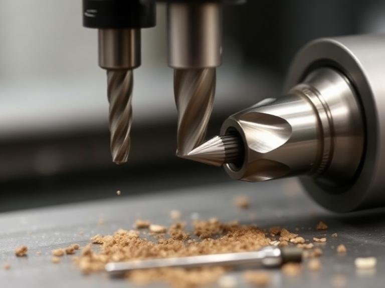
Understanding exactly how an incorrect pre-hole dimension triggers catastrophic failure is essential for any production facility seeking to eliminate scrap and maintain spindle uptime. When a pre-drill hole is undersized by a fraction of a millimeter, cutting forces skyrocket exponentially rather than linearly. Conversely, an oversized hole strips thread shear strength, leading to scrap parts that fail quality inspections. Knowing the exact mechanics of why improper drill size causes tap breakage separates profitable machine shops from operations that bleed money on broken tools and electrical discharge machining (EDM) tap extraction.
In this engineering guide, we examine the physics of thread engagement, break down the six distinct mechanical reasons why wrong drill size causes tap breakage, and provide actionable hole preparation standards to optimize tool life and thread integrity.
Quick Answer: Why Wrong Drill Size Causes Tap Breakage
A wrong drill size causes tap breakage primarily because an undersized pre-drill hole dramatically increases the percentage of thread engagement (pushing it above 75% or 80%). This overload causes cutting torque to spike beyond the core shear strength of the tap steel. When the pre-drill hole is too small, excessive core friction, severe chip packing in the flutes, chamfer overload on the leading cutting edges, and premature work-hardening in strain-sensitive alloys combine to wedge the tool solid. The spindle rotational force snaps the brittle high-speed steel or solid carbide body instantly. To eliminate breakage, machinists must calculate the pre-drill hole targeting a realistic 60% to 70% thread engagement rather than chasing an unnecessary 100% full thread depth.
Table of Contents
- 1. The Mechanics: How Drill Sizing Dictates Tapping Torque
- 2. Quick Summary Table: 6 Causes of Failure
- 3. Reason 1: Exponential Torque Overload from Excessive Thread Engagement
- 4. Reason 2: Severe Chip Compaction and Flute Starvation
- 5. Reason 3: Work-Hardening of the Minor Diameter During Drilling
- 6. Reason 4: Concentrated Stress on the Tap Chamfer Lead
- 7. Reason 5: Radial Deflection and Bell-Mouthed Pre-Holes
- 8. Reason 6: Cold Extrusion Jamming in Roll Form Tapping
- 9. Comparison Table: Under-Drilled vs. Optimal vs. Over-Drilled Holes
- 10. Pros and Cons: 75% Thread Depth vs. 60-65% Thread Depth
- 11. Who Should Use Engineered Sizing (And Who Does Not Need It)
- 12. Common Hole Preparation Mistakes on the Shop Floor
- 13. Buying and Tooling Considerations for Production Tapping
- 14. Expert Recommendation from MisolTap
- 15. Frequently Asked Questions (FAQ)
- 16. Authoritative References
1. The Mechanics: How Drill Sizing Dictates Tapping Torque
A tap is a delicate multi-point cutting tool engineered to slice helical grooves along the walls of a pre-drilled cylinder. The relationship between the drilled hole diameter and the tap’s major and pitch diameters is governed by the percentage of thread depth. Standard machinists often assume that a 100% full thread profile provides maximum joint strength. In modern manufacturing, this assumption is completely false.
Thread theory proves that a 60% to 70% thread depth provides over 95% of the ultimate tensile and stripping strength of a 100% thread, while requiring less than half the cutting torque to generate. When an undersized drill bit is used, the pre-hole diameter approaches the tap’s root (minor) diameter. As thread engagement climbs from 65% to 85%, cutting resistance does not increase steadily—it surges drastically. The tap core is forced to displace and evacuate a massive volume of chips through narrow flutes. When the required driving torque exceeds the ultimate torsional strength of the tap core, the tool shears instantly.
2. Quick Summary Table: 6 Causes of Failure
| Failure Mechanism | Drill Sizing Condition | Primary Physical Cause | Resulting Failure Mode |
|---|---|---|---|
| Torque Overload | Undersized Pre-Drill | Excessive thread engagement (>80%) | Clean torsional snap at the relief neck |
| Chip Compaction | Undersized Pre-Drill | Flute volume exceeded by chip volume | Flute wedging, teeth chipping, instant seizure |
| Work-Hardening | Worn / Undersized Drill | Friction rubbing hardens hole perimeter | Micro-chipping on leading cutting teeth |
| Chamfer Overload | Undersized Pre-Drill | Leading 2-3 teeth taking 300% chip load | Leading tooth shear and thread stripping |
| Radial Binding | Wandering / Drifting Drill | Angular misalignment and bell-mouthing | Bending fatigue and off-axis tap snapping |
| Forming Seizure | Undersized for Roll Tap | Zero relief displacement during plastic forming | Complete hydrostatic lock inside the hole |
3. Reason 1: Exponential Torque Overload from Excessive Thread Engagement
The foremost reason drill size causes tap breakage is the direct correlation between minor hole diameter and torque buildup. In our testing on 4140 pre-hardened alloy steel, reducing the pre-drill diameter by merely 0.2mm on an M10x1.5 thread increased the required cutting torque by over 140%.
Taps are manufactured from hardened High-Speed Steel (HSS-E, HSS-PM) or solid micrograin carbide. While these materials exhibit exceptional wear resistance and high compressive strength, they have limited torsional elasticity. When a drill is undersized, the cutting edges must cut full root-to-crest profiles. The spindle continues rotating while the tap teeth encounter immense cutting resistance, creating a massive torsional shear stress that instantly exceeds the cross-sectional shear limit of the tap’s web.
4. Reason 2: Severe Chip Compaction and Flute Starvation
A tap possesses a fixed flute volume designed to evacuate a calculated volume of metal per revolution. When a pre-drill hole is appropriately sized according to a precision tap and drill size chart, chips shear cleanly into tight curls and exit the hole via spiral or straight flutes.
When the hole is too small, the volume of material removed increases drastically. The chips quickly outgrow the physical volume of the tap flutes. Unable to escape, the metal chips pack into dense solid masses between the tap flutes and the workpiece wall. This phenomenon, known as chip compaction, creates extreme radial pressure. The tap binds against its own chips, stalling the rotation while the machine spindle continues driving, resulting in immediate structural failure.
5. Reason 3: Work-Hardening of the Minor Diameter During Drilling
Drill sizing errors are not merely mathematical; they are frequently mechanical. If an operator utilizes a dull drill or an incorrect feed rate to achieve a tight pre-drill diameter, the drill rubs and burnishes the inner wall of the hole rather than shearing the stock cleanly.
In materials like 304/316 stainless steel, Inconel, and titanium alloys, this rubbing action instantly work-hardens the minor diameter, forming a rock-hard glaze on the hole surface. When the tap enters, its cutting teeth hit a case-hardened crust that is significantly harder than the bulk material. The tap teeth dull immediately, cutting temperatures skyrocket, friction locks the tap in place, and the tool snaps. Selecting the best material for thread taps helps resist abrasive wear, but it cannot overcome a severely work-hardened pre-hole.
6. Reason 4: Concentrated Stress on the Tap Chamfer Lead
Every cutting tap features a chamfer lead (taper, plug, or bottoming) that distributes the progressive cutting load across multiple teeth. In a properly sized hole, each chamfer tooth cuts a thin, manageable chip thickness. To understand how lead geometry impacts cutting pressure, machinists should review the physical differences in a plug tap vs thread tap.
When the pre-hole is undersized, the first one or two teeth of the chamfer bear an excessive depth of cut. Instead of slicing away 0.05mm of stock per tooth, the lead teeth are forced to hog out massive amounts of solid metal. This localized stress concentration causes micro-fractures in the carbide matrix or high-speed steel grain structure. Once the leading tooth fractures, the chipped tooth jams into the cut, creating an abrupt shock load that destroys the entire tool.
7. Reason 5: Radial Deflection and Bell-Mouthed Pre-Holes
A wrong drill size issue often manifests as inconsistent hole geometry rather than a uniform cylindrical error. When a drill bit is undersized or improperly ground, it flexes and wanders upon entering the material, creating a bell-mouthed entry and a tapered, undersized bottom.
As the tap travels deeper down the hole, it transitions from a loose, oversized entry to an increasingly choked, undersized diameter at the bottom. This progressive taper causes severe radial deflection. The tap is forced to cut off-axis while simultaneously fighting an undersized minor diameter. Taps have virtually zero flexural tolerance; the combination of bending moments and cutting torque snaps the tool body cleanly at the shank-to-flute transition.
8. Reason 6: Cold Extrusion Jamming in Roll Form Tapping
The most devastating application of wrong drill size occurs in cold forming (roll forming) operations. Unlike standard cutting taps that produce chips, thread forming taps displace metal plastically, pushing material from the root into the crest of the thread profile.
Because no chips are cut, the pre-drill hole for a forming tap must be substantially larger than the pre-drill hole for a cutting tap. For example, as outlined in an authoritative 1/2 thread tap size chart, a cutting tap might demand a 27/64-inch hole, whereas a forming tap requires a 29/64-inch hole. If an operator inadvertently uses a cutting-tap drill size for a forming tap, the displaced metal has nowhere to flow. The extreme hydraulic and mechanical pressure locks the forming lobes solid within seconds, snapping the tap and frequently damaging the machine tool spindle.
9. Comparison Table: Under-Drilled vs. Optimal vs. Over-Drilled Holes
| Parameter | Undersized Hole (<60% Dia) | Optimal Hole (65%-70% Depth) | Oversized Hole (>80% Dia) |
|---|---|---|---|
| Thread Engagement % | 80% – 100% Full Thread | 65% – 70% Engineered Profile | 40% – 55% Shallow Profile |
| Cutting Torque | Extremely High (200% – 350%) | Baseline Nominal (100%) | Very Low (40% – 60%) |
| Tap Breakage Risk | Critical / Imminent Failure | Minimal / Predictable Tool Life | Extremely Low |
| Thread Stripping Strength | 100% (Over-engineered) | 95% – 98% (Meets all Mil/Aero specs) | Fails Go/No-Go Gauge / Strips easily |
| Tool Wear Rate | Rapid edge breakdown and chipping | Even, predictable flank wear | Minimal wear, but scrap parts generated |
10. Pros and Cons: 75% Thread Depth vs. 60-65% Thread Depth
| 75% Full Thread Depth (Old Rule of Thumb) | 60% – 65% Engineered Thread Depth (Modern Standard) |
|---|---|
| Pro: Traditional standard recognized on older legacy drawings. | Pro: Reduces tapping torque by up to 40%, drastically increasing tool life. |
| Con: Generates extreme torque that frequently causes tap breakage in CNC setups. | Pro: Retains full mechanical fastener holding strength in standard length-of-engagement holes. |
| Con: Forces high scrap rates in tough alloys like titanium, 17-4 PH, and duplex stainless. | Pro: Facilitates superior coolant delivery and effortless chip evacuation. |
| Con: Provides virtually zero added functional joint strength compared to a 65% thread. | Con: Requires engineering approval if legacy prints explicitly demand older 75% minor diameters. |
11. Who Should Use Engineered Sizing (And Who Does Not Need It)
For commercial users and CNC production facilities: Implementing precise, calculated pre-drill diameters based on modern tooling charts is non-negotiable. When running automated lights-out machining or high-volume threading cycles, a broken tap halts entire production lines and ruins high-value components. Using industrial-grade tooling from a certified din371 thread tap supplier paired with exact hole sizes guarantees stable tool life across thousands of cycles.
Who does not need it: Hobbyists performing manual maintenance on soft structural plastics, nylon, or low-density aluminum alloys have wider operating tolerances. In those situations, slight hole variations can be managed with careful hand-feel and manual tapping cycles. However, the moment you move into rigid metals, understanding how to tap threads in metal with exact pre-hole diameters becomes critical.
12. Common Hole Preparation Mistakes on the Shop Floor
From our engineering consultations, we regularly observe machinists make these critical mistakes during hole preparation:
- Relying on Generic Fractional Charts: Grabbing a generic chart off a shop wall that assumes a 75% thread in mild steel, then using that exact same drill bit for 316 stainless steel or Inconel 718. Tough materials must be drilled larger (targeting 60-65% thread depth).
- Failing to Account for Drill Runout: Using worn ER collets or standard drill chucks that induce 0.05mm runout. The drill cuts an oversized hole at the top and an irregular taper at the bottom, creating uneven loading on the tap flutes.
- Confusing Cut Tap and Form Tap Charts: Using a cutting tap drill chart when mounting a thread forming tap. This is a catastrophic error that guarantees instant tool breakage.
- Ignoring Chamfer Hole Preparation: Drilling a straight hole without a lead-in chamfer prior to tapping. Taps require a 90-degree to 120-degree chamfer slightly larger than the major thread diameter to guide the lead teeth smoothly into the cut.
13. Buying and Tooling Considerations for Production Tapping
When selecting your cutting systems, apply these commercial guidelines to prevent tooling failures:
| Tooling Factor | Standard Requirement | Why It Protects Against Breakage |
|---|---|---|
| Drill Tolerance | Use carbide drills with m7 or h7 diameter tolerances. | Eliminates hole diameter variation, ensuring consistent thread percentage. |
| Tap Geometry | Select spiral point for through-holes; spiral flute for blind holes. | Ensures chips are directed away from the cut, preventing chip-packing seizure. |
| Machine Selection | Match machine taps to rigid synchronous tapping holders. | Understanding machine tap vs hand tap features prevents improper mechanical driving. |
| Coolant Lubricity | High-pressure water-soluble oil (>8% concentration) or tapping paste. | Reduces friction torque on the tap margins and flutes during high-speed threading. |
14. Expert Recommendation from MisolTap
The MisolTap Engineering Verdict: Stop drilling for 75% or 80% thread engagement in difficult alloys. In over 15 years of metallurgical and cutting analysis, we have proven that moving to a 65% thread depth reduces tapping torque by 30% to 45% while maintaining full tensile pull-out strength. Always verify your actual drilled minor diameter with a bore gauge or plug gauge before running a tap into a production workpiece.
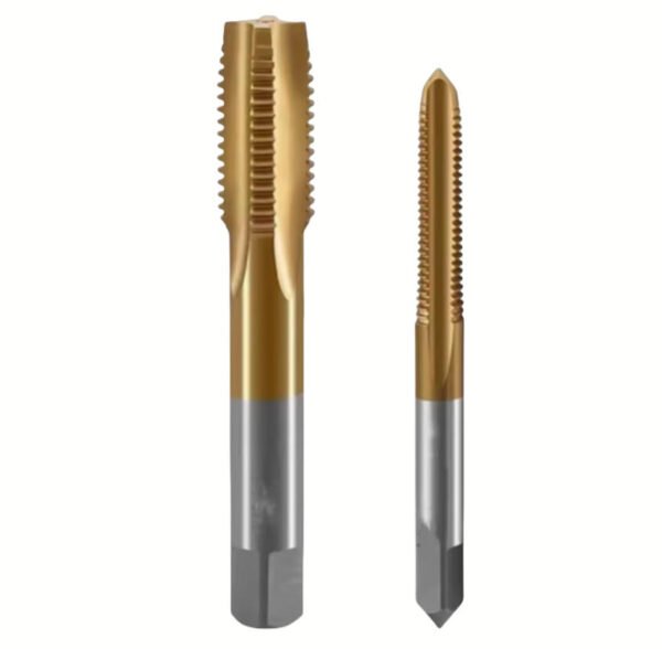
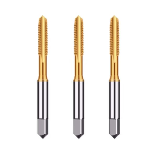
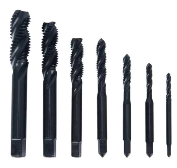
MisolTap: Precision Threading Tool Solutions
Since our founding in 2005, MisolTap has established itself as a leading Chinese manufacturer of high-performance thread cutting tools. We integrate R&D, production, and global sales into a seamless operation, providing our clients with robust and precise threading solutions tailored to modern manufacturing needs.
Whether you need custom-engineered taps for aerospace alloys, standard DIN and ISO threading tools, or specialized forming taps, our technical engineering team provides the precise cutting parameters and tooling geometries needed to completely eliminate tap breakage in your facility.
15. Frequently Asked Questions (FAQ)
How does drill size cause tap breakage during CNC tapping?
An undersized drill bit forces the tap to cut too much material, raising thread engagement above safe operating levels (often over 80%). This causes an exponential spike in cutting torque and causes chips to pack tightly into the flutes. When the torque required to shear the metal exceeds the torsional strength of the tap, the tool breaks instantly.
What is the formula to calculate the correct drill size for a cutting tap?
For metric cutting taps, the standard formula for a 75% thread is: Drill Size = Major Diameter – Pitch. For example, for an M8x1.25 tap: 8mm – 1.25mm = 6.75mm (standard 6.8mm drill). For high-strength alloys, machinists typically use: Drill Size = Major Diameter – (0.929 x Pitch x Desired % Engagement / 100).
Why do forming taps require a larger drill size than cutting taps?
Forming taps do not produce chips; they displace metal through plastic deformation, pushing stock from the root up into the crest. Because no material is removed from the hole, an undersized hole leaves no room for the displaced metal, resulting in extreme hydraulic lock and immediate tap breakage.
Does a 100% thread depth provide double the strength of a 50% thread?
No. Fastener pull-out tests prove that a 60% to 65% thread depth provides over 95% of the ultimate shear and tensile strength of a 100% thread in standard bolt engagements. Increasing thread depth beyond 70% yields negligible strength gains while increasing tapping torque by several hundred percent.
16. Authoritative References
To ensure our machining standards and engineering data meet international manufacturing requirements, we reference the following authoritative organizations:
- ASME (American Society of Mechanical Engineers) – Standard ASME B1.1: Unified Inch Screw Threads and Standard Minor Diameter Tolerances.
- ISO (International Organization for Standardization) – ISO 68-1 and ISO 261: General purpose metric screw threads, basic profiles, and manufacturing tolerances.
- Society of Manufacturing Engineers (SME) – Technical resources on cutting tool mechanics, torque modeling, and chip evacuation dynamics in production machining.