
In high-volume CNC machining and precision manufacturing, few operations are as high-risk as thread tapping. It is typically one of the final operations performed on a workpiece. If a tap shatters inside a block of aerospace-grade titanium, or seizes in a complex 316 stainless steel manifold, the entire multi-thousand-dollar part is often scrapped. While tooling engineers spend exhaustive hours optimizing cutting speeds, feeds, and high-pressure coolant concentrations, the root cause of tap failure frequently lies in a foundational, yet highly misunderstood metric: selecting the incorrect drill bit size.
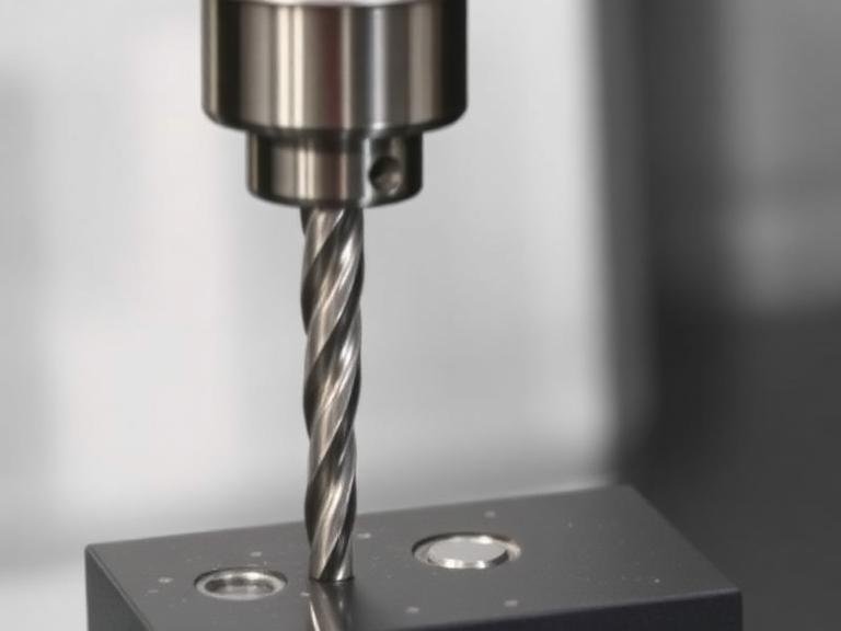
From our experience manufacturing precision thread cutting tools at MisolTap since 1991, we continually analyze tool failure reports from machine shops, automotive manufacturers, and industrial buyers worldwide. In most professional situations, premature tap wear, oversized threads, and catastrophic tool breakage are not caused by defective taps. Instead, they are caused by a misunderstanding of how a common tap drill size interacts with specific workpiece materials, thread standards, and tap geometry. Machinists often rely on outdated wall charts without adjusting for modern cutting dynamics. In this article, we will detail the nine most critical mistakes buyers and engineers make regarding tap drill sizes, and provide actionable, commercial-grade solutions to ensure precision threading and extended tool life.
Quick Answer: What is a Common Tap Drill Size and Where Do Machinists Fail?
A common tap drill size refers to the specific diameter of a twist drill bit used to create a pilot hole before a thread tap is introduced to cut or form the internal threads. The most devastating mistake machinists make is blindly following standard shop wall charts that recommend a 75% thread engagement for all materials. We recommend reducing thread engagement to 60-65% for tough materials (like stainless steel, Inconel, or titanium) by increasing the drill size slightly. This minor reduction significantly lowers cutting torque, prevents tap breakage, and extends tool life, while still providing 95% of the functional holding strength of a fully engaged thread.
Table of Contents
- Understanding the Fundamentals of Tap Drill Sizes
- Quick Summary: 9 Common Mistakes
- 1. Defaulting to 75% Thread Engagement
- 2. Confusing Cut Tapping with Form Tapping Sizes
- 3. Ignoring Workpiece Material Elasticity
- 4. Failing to Account for Drill Runout
- 5. Confusing Nominal Size with Drill Size
- 6. Misunderstanding Pipe Thread Requirements
- 7. Overlooking the Impact of Deep Blind Holes
- 8. Work-Hardening the Hole with Dull Drills
- 9. Selecting Tooling Based Only on Upfront Price
- Pros and Cons: High vs. Low Thread Engagement
- Comparison: Cut Tapping vs. Form Tapping Requirements
- Buying Guide for Precision Threading Tools
- Expert Recommendation & Manufacturing Insight
- Frequently Asked Questions
- Authoritative References
Understanding the Fundamentals of Tap Drill Sizes
Before examining specific operational failures, we must define the mechanical relationship between the drilled hole and the thread. A thread tap does not cut the entire volume of a hole; it only cuts the internal thread profile (the “V” shape) into the wall of a pre-existing hole. If the pilot hole is too small, the tap is forced to remove too much base material. This causes massive friction, extreme torque spikes, and eventual catastrophic breakage. If the hole is too large, the tap removes too little material, resulting in shallow, truncated threads that will strip under structural load.
To determine the correct drill bit, professionals consult a tap and drill size chart. However, these charts are merely starting points. The true optimal size depends on three dynamic variables: the desired thread percentage, the specific machinability of the workpiece material, and whether the tap physically removes material (a cut tap) or displaces material (a form/roll tap). Treating the chart as an absolute rule rather than a baseline guide is where production errors begin.
Quick Summary: 9 Common Mistakes
| Mistake | Root Cause | Professional Solution |
|---|---|---|
| 1. Defaulting to 75% Thread | Relying strictly on outdated shop wall charts for all jobs. | Drop to 60-65% engagement for tough materials to lower torque. |
| 2. Mixing Cut vs. Form Taps | Misunderstanding how metal displacement works. | Always use a significantly larger drill for form/roll taps. |
| 3. Ignoring Material Elasticity | Treating aluminum the same as titanium. | Adjust drill size based on material spring-back and hardness. |
| 4. Ignoring Drill Runout | Poor machine spindle concentricity or lack of spot drilling. | Measure the actual hole size with pin gauges, not just the drill bit. |
| 5. Confusing Nominal Size | Assuming a 1/2″ tap needs a 1/2″ drilled hole. | Calculate: Drill Size = Nominal Thread Diameter – Pitch. |
| 6. Pipe Thread Miscalculations | Misunderstanding tapered thread profiles (NPT/BSP). | Use specific taper reamers or step drills prior to tapping. |
| 7. Deep Blind Hole Issues | Chip packing at the bottom of the hole. | Increase drill size slightly; specify spiral flute taps. |
| 8. Work-Hardening the Hole | Using dull drills or incorrect slow feed rates. | Maintain aggressive feed rates and sharp drill cutting edges. |
| 9. Price-Only Purchasing | Procurement buying generic, low-cost commodity tools. | Evaluate total tooling cost, including tool life and scrap rates. |
1. Defaulting to 75% Thread Engagement for All Materials
Observation: We frequently see machine shops defaulting to a drill size that yields a 75% thread engagement across all materials, simply because it is the standard value listed in legacy machinist handbooks.
Why It Happens: In decades past, 75% engagement was considered the ideal balance between fastener holding strength and tap life for mild steel and aluminum. However, extensive engineering testing shows that a 60% thread engagement provides roughly 95% of the holding strength of a 75% thread, but requires significantly less torque to machine.
Professional Approach: When tapping difficult-to-machine materials like Inconel, 316 stainless steel, or aerospace titanium, maintaining a 75% thread engagement drastically increases tool wear and the risk of the tap seizing and breaking. We recommend increasing your common tap drill size slightly to achieve a 60% to 65% thread engagement in tough alloys. This minor adjustment slashes cutting torque by up to 50%, vastly extending the life of your precision threading tools without compromising the mechanical integrity of the joint.
2. Confusing Cut Tapping with Form Tapping Drill Sizes
Observation: Tooling engineers occasionally use the standard cut tap drill size when switching a manufacturing process over to a roll tap (form tap), resulting in immediate, catastrophic tap destruction on the very first cycle.
Why It Happens: Cut taps feature flutes and sharp cutting edges that physically shear metal away to form the thread. Form taps (or roll taps) have no cutting edges; they cold-forge the material, displacing it outward and inward to form the thread peaks. Because material is displaced inward, form tapping requires a significantly larger pre-drilled hole than cut tapping.
Professional Approach: Never interchange these drill sizes. If you use a cut tap drill size for a form tap, there will be too much solid material in the hole, causing the tap to seize and snap instantly. Always consult specific manufacturer data for form tapping drill sizes. Understanding the different types of thread taps is critical before locking in your CNC programming and tool paths.
3. Ignoring Workpiece Material Properties and Elasticity
Observation: A production run shifts from 6061 Aluminum to 304 Stainless Steel, but the programmer leaves the pre-drill size identical in the CAM software.
Why It Happens: Operators assume that an M8x1.25 thread is mechanically the same regardless of the substrate. This completely ignores the material’s elasticity, spring-back characteristics, and tensile strength.
Professional Approach: Softer materials like aluminum or brass tend to cut very cleanly and close to the actual drill diameter. However, materials with high elasticity (like certain plastics or titanium) will “spring back” after the drill retracts. This results in a hole that is actually microscopically smaller than the drill bit used. In these scenarios, you must compensate by using a marginally larger drill bit or employing a rigid, high-performance solid carbide drill to ensure dimensional accuracy. Choosing the best material for thread taps is irrelevant if the hole dimension is compromised by material spring-back before the tap even enters.
4. Failing to Account for Drill Wander and Runout
Observation: The theoretically correct drill bit is selected, yet the resulting tapped threads are constantly failing go/no-go gauge inspections for being oversized or sloppy.
Why It Happens: A drill bit is not a perfectly rigid tool. If the CNC spindle has high Total Indicator Runout (TIR), or if the drill wanders upon entry because the hole wasn’t properly spot-drilled, it will cut an oversized, bell-mouthed, or oval hole. When the tap enters an oversized hole, the resulting threads will have a lower thread percentage than calculated, leading to a loose, out-of-tolerance fit.
Professional Approach: You must measure the actual drilled hole size using a precision pin gauge before tapping, not just read the diameter stamped on the drill shank. If your drilled holes are consistently oversized, you must evaluate your tool holding (switching to hydraulic or shrink-fit chucks), verify spindle concentricity, and ensure proper spot drilling geometry.
5. Confusing Nominal Thread Size with Drill Size
Observation: Inexplicably, beginners and inexperienced operators sometimes attempt to drill a 1/2″ hole for a 1/2″-13 UNC thread tap.
Why It Happens: This represents a fundamental misunderstanding of thread geometry. The nominal size (e.g., 1/2″) represents the major diameter (the outside diameter of the male fastener). The tap drill must create a hole corresponding to the minor diameter (the inner root of the thread).
Professional Approach: The simplest rule of thumb for metric threads is to subtract the pitch from the nominal diameter. For example, for an M8x1.25 thread, the formula is 8 – 1.25 = 6.75mm tap drill size. For fractional imperial sizes, operators must use a verified 1/2 thread tap size chart. In actual production, machine operators must be trained to verify the difference between major, pitch, and minor diameters before hitting cycle start.
6. Misunderstanding Pipe Thread Requirements
Observation: Tapping pipe threads (such as NPT or BSPT) often results in severe galling, torn threads, or taps breaking halfway down the hole.
Why It Happens: Tapered pipe threads are designed to seal by wedging together. If a standard straight cylindrical hole is drilled, the tap encounters an exponentially increasing volume of material the deeper it goes into the hole, causing massive torque spikes and preventing chip evacuation.
Professional Approach: When working with NPT or tapered threads, utilizing a taper reamer after standard drilling, or using a specialized step-drill, significantly reduces the cutting load on the tap by pre-forming the taper. For commercial buyers manufacturing fluid fittings or manifolds, reviewing a specific pipe thread tap size chart is mandatory to prevent scrap and ensure pressure-tight seals.
7. Overlooking the Impact of Deep Blind Holes
Observation: Premium spiral flute taps are snapping in deep blind holes (depth greater than 2.5x diameter), even when the correct drill size is used.
Why It Happens: In deep blind holes, chip evacuation is the enemy. Even if the drill size is mathematically correct for a 70% thread, the sheer volume of chips generated cannot escape the flutes quickly enough. The chips pack tightly at the bottom of the hole, binding the tap and causing it to snap under rotational torque.
Professional Approach: For deep blind holes, two things must happen: First, slightly increase the tap drill size to lower the volume of chips generated. Second, ensure you are using a high-helix spiral flute tap specifically designed to pull chips upward and out of the hole, rather than a spiral point tap which pushes chips forward. Understanding how to tap threads in metal requires matching the hole type (blind vs. through) to the correct flute geometry.
8. Work-Hardening the Hole with Dull Drills
Observation: Premium taps from MisolTap are wearing out prematurely, squealing during cutting, or chipping on the very first few threads of entry.
Why It Happens: If a drill bit is dull, or if it is fed too slowly through work-hardening materials like 300-series stainless steel or aerospace superalloys, it generates excessive heat. It “rubs” the material rather than shearing it cleanly. This friction heavily work-hardens the walls of the hole. By the time the tap enters, it is trying to cut a surface that has been case-hardened by the previous drilling operation.
Professional Approach: The tapping operation is entirely dependent on the quality of the drilling operation. Maintain aggressive feed rates during drilling to get beneath the work-hardening zone, use adequate coolant, and replace drill bits before they show significant wear. If you are struggling with establishing the correct feeds and speeds, consult a technical guide on proper drilling speed for metal.
9. Selecting Drills and Taps Based Only on Upfront Price
Observation: Procurement managers frequently source the cheapest generic drill bits and machine taps available to lower upfront tooling purchase orders.
Why It Happens: Buyers often view cutting tools as basic commodities, failing to recognize that a $10 saving on a thread tap can cause a $5,000 machined casing to be scrapped.
Professional Approach: A low-cost tap is rarely the lowest-cost solution. Tool life, thread quality, cycle time, breakage risk, rework labor, and machine downtime significantly affect the total tooling cost per threaded hole. A precision-ground tap made from premium High-Speed Steel (HSS-E or Powder Metallurgy) with a specialized coating (like TiCN or TiAlN) will vastly outperform generic tooling, providing stable, predictable batch consistency. It is also vital to distinguish between tool styles; using a cheap hand tap in a rigid CNC spindle will fail instantly. Understand the machine tap vs hand tap dynamic before approving purchase orders.
Pros and Cons: High vs. Low Thread Engagement
When selecting your common tap drill size, you must strategically decide what thread percentage to target based on the application. Here is how professionals evaluate the trade-off:
| Thread Engagement Target | Pros (Advantages) | Cons (Limitations) |
|---|---|---|
| High (70% – 75%) (Requires a smaller drill bit) | Maximum theoretical fastener holding strength; ideal for soft materials (aluminum, plastics, brass); meets standard specification for many legacy aerospace drawings. | High cutting torque; rapid tap wear; massive risk of tap breakage in tough materials; difficult chip evacuation in deep holes. |
| Low (60% – 65%) (Requires a larger drill bit) | Significantly lower cutting torque; longer tool life; vastly reduced risk of tap breakage; much easier to machine stainless steel and titanium alloys. | Slightly reduced fastener pull-out strength; may fail strict military go/no-go gauge tolerances if the drill runout is not carefully monitored. |
Comparison: Cut Tapping vs. Form Tapping Requirements
| Machining Factor | Cut Tapping | Form (Roll) Tapping |
|---|---|---|
| Mechanism of Action | Shears and removes material to create threads. | Displaces material to form threads (cold forging). |
| Tap Drill Size Requirement | Standard size (hole closely matches the minor diameter). | Significantly larger (hole must accommodate inward displaced material). |
| Chip Production | Generates continuous or broken chips (requires evacuation). | Chipless (highly ideal for deep blind holes). |
| Material Suitability | Works on all materials, including brittle cast iron and plastics. | Only works on highly ductile materials (Aluminum, low-carbon steel, brass). |
| Resulting Thread Strength | Standard baseline strength. | Higher strength due to work-hardened grain flow in the thread roots. |
Buying Guide for Precision Threading Tools
For commercial buyers, procurement managers, and manufacturing engineers, evaluating a thread tap manufacturer goes beyond looking at a catalog’s price list. When sourcing threading tools for production environments, we recommend analyzing the following criteria:
| Evaluation Criteria | What to Look For | Why It Matters to Production |
|---|---|---|
| Manufacturing Equipment | Multi-axis CNC grinding capabilities (e.g., 5-axis machines). | Ensures perfect cutting edge geometry, precise relief angles, and pitch consistency across large production batches. |
| Heat Treatment | In-house vacuum heat treatment facilities. | Taps must perfectly balance extreme surface hardness for wear resistance with core toughness to prevent snapping under torque. |
| Base Material Selection | HSS-E (Cobalt-alloyed) or PM (Powder Metallurgy) High-Speed Steel. | Standard HSS dulls rapidly in tough modern alloys. PM steel offers superior wear life, edge stability, and heat resistance. |
| Quality Certifications | ISO 9001:2015, SGS Audited, TUV Rheinland. | Guarantees that the manufacturer has formalized, repeatable quality control and dimensional inspection protocols. |
Expert Recommendation & Manufacturing Insight
In most professional situations, we recommend that CNC programmers and tooling engineers stop blindly relying on generic, decades-old tap drill charts. You must evaluate your specific application holistically. If you are tapping a deep blind hole in 316 stainless steel, proactively increase your tap drill size to drop the thread engagement to 60-65%. Ensure your drill bit is sharp and fed aggressively to prevent work-hardening the hole, and select a premium spiral flute tap made from cobalt-alloyed high-speed steel to evacuate the chips cleanly.
At MisolTap (MisolGroup), we do not simply cut a basic thread profile onto a piece of steel. Since 1991, we have operated with the philosophy that thread tap performance relies on exact geometry, material integrity, and flawless execution. We operate more than 50 sets of 5-axis CNC grinding machines and maintain our own in-house vacuum heat treatment capabilities. This integrated production allows us to control the dimensional consistency, thread profile accuracy, and cutting edge condition of every tool that leaves our facility. For commercial buyers, evaluating a supplier based on this level of production control is critical. A tap that cuts perfectly on Monday but breaks on Thursday due to poor batch consistency destroys your manufacturing profitability.
Optimize Your Threading Operations Today
Stop losing money to broken taps, oversized threads, and scrapped parts. Partner with a precision thread tap manufacturer that truly understands the nuances of industrial CNC machining.
Contact MisolTap to discuss your thread tap requirements, application conditions, tooling specifications, or custom threading tool needs.Contact MisolTap for Tooling Selection and Quotation
Frequently Asked Questions
How do I calculate the correct tap drill size for a standard metric thread?
The generally accepted, simplified formula for a standard metric cut tap (resulting in approximately 75% thread engagement) is: Nominal Thread Diameter minus the Thread Pitch. For example, for an M10x1.5 thread, the formula is 10 – 1.5 = 8.5mm tap drill size. However, for tough materials, professionals often increase this size slightly to lower cutting torque.
Can I use the same drill bit size for a form tap and a cut tap?
No, absolutely not. Form taps (roll taps) displace material rather than cutting it. Because they push the material inward to form the thread peaks, they require a significantly larger pre-drilled hole. Using a cut tap drill size for a form tap will result in too much material in the hole, leading to immediate tap breakage.
What thread percentage should I aim for when machining tough materials like Titanium or Inconel?
While 75% thread engagement is a common historical standard, machining tough materials at 75% causes excessive torque and frequent tap breakage. Industry best practices recommend dropping the engagement to 60% to 65% by using a slightly larger drill bit. This dramatically extends tool life while maintaining sufficient functional fastener strength for most applications.
Why do my tapped holes consistently fail go/no-go gauge inspections?
If your threads are oversized, it is rarely the fault of the tap itself. Oversized threads are typically caused by a pre-drilled hole that is too large (due to drill wander or machine spindle runout), an incorrect feed rate on the CNC machine causing the tap to act like a reamer, or chip packing in a blind hole that pushes the tap off-center.
How does MisolTap ensure batch consistency in their thread taps?
MisolTap ensures exceptional consistency by integrating R&D, manufacturing, and quality control entirely in-house. We utilize over 50 sets of modern 5-axis CNC grinding machines for exact geometric repetition, maintain our own vacuum heat treatment processes to ensure uniform core and surface hardness, and operate under strict ISO 9001:2015 certified quality management systems.
Authoritative References
- American Society of Mechanical Engineers (ASME) – B1.1 Unified Inch Screw Threads and Drill Sizes
- International Organization for Standardization (ISO) – ISO 68-1: General Purpose Metric Screw Threads
- National Institute of Standards and Technology (NIST) – Manufacturing Metrology and Hole Tolerancing Guidelines